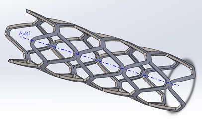
Figure 1 Rhombus structure of stent with 4 rhombus units – 8 struts [11]
Figure 1 Rhombus structure of stent with 4 rhombus units – 8 struts [11]
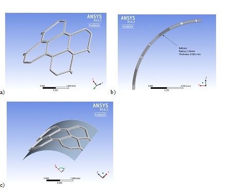
Figure 2 a) Reduced stent model used for axisymmetric structural analysis b) the reduced balloon model along the length c) The reduced stent with balloon combined model used for axisymmetric structural analysis.
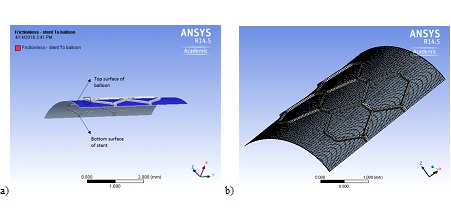
Figure 3 a) frictionless contact surfaces b) meshed stent and artery used for analysis
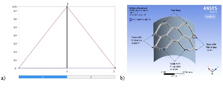
Figure 4 a) Graph showing the displacement boundary condition steps b) Free faces and faces with frictionless supports used in axisymmetric analysis
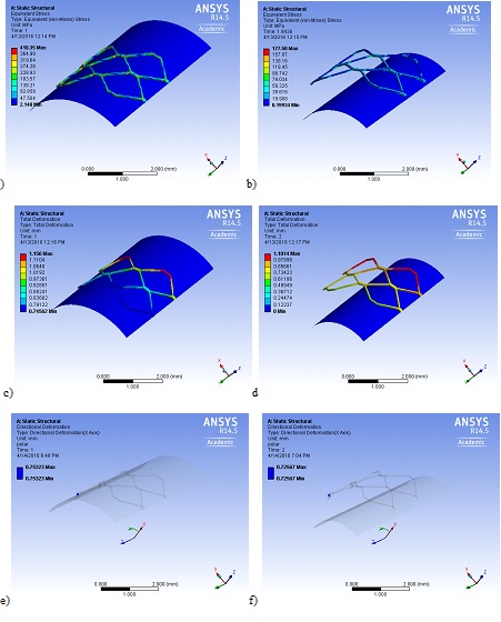
Figure 5 SS 316L: a) Maximum equivalent Von Mises stress when the balloon is fully expanded b) residual stress retained by the stent after deflation of balloon c) maximum total deformation at fully expanded condition d) total deformation due to recoiling when the balloon deflates e) Maximum displacement along X at fully expanded balloon and f) displacement along X after recoiling.
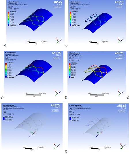
Figure 6CoCrFeNiMn: a) Maximum equivalent Von Mises stress when the balloon is fully expanded b) residual stress retained by the stent after deflation of balloon c) maximum total deformation at fully expanded condition d) total deformation due to recoiling when the balloon deflates e) Maximum displacement along X at fully expanded balloon and f) displacement along X after recoiling.
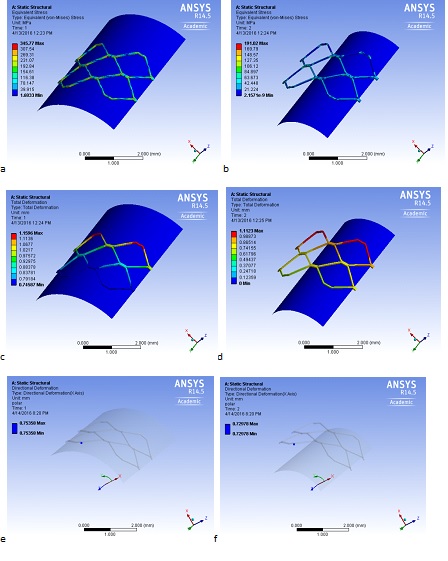
Figure 7 Al0.1CoCrFeNi: a) Maximum equivalent Von Mises stress when the balloon is fully expanded b) residual stress retained by the stent after deflation of balloon c) maximum total deformation at fully expanded condition d) total deformation due to recoiling when the balloon deflates e) Maximum displacement along X at fully expanded balloon and f) displacement along X after recoiling.
Parameters |
Values |
Length |
15 mm |
Outer diameter |
3.0mm |
Strut width |
0.05mm |
Strut thickness |
0.05 mm |
Longest diagonal of the rhombus |
1.62mm |
Shortest diagonal of the rhombus |
1.18 mm |
No. of units along circumference |
8 |
Table 1. Dimensions of the stent model
Material |
Yield strength MPa |
Ultimate strength MPa |
Young's modulus GPa |
Tangent modulus GPa |
Density kg/m3 |
Poisson's ratio |
SS 316L |
190 |
490 |
193 |
1.93 |
8000 |
0.3 |
CoCrFeNiMn |
216 |
475 |
189 |
0.643 |
7954 |
0.3 |
Al0.1CoCrFeNi |
212 |
570 |
203 |
0.843 |
7950 |
0.3 |
Table 2. Mechanical properties of SS 316L and Al0.1CoCrFeNi and CoCrFeNiMn HEAs added to ANSYS Workbench library
Steps |
Time [s] |
X [mm] |
Y [mm] |
Z [mm] |
1 |
0. |
0. |
0. |
0. |
1. |
0.75 |
|||
2 |
2. |
0. |
= 0. |
= 0. |
Table 3: Displacement boundary in cylindrical coordinate system for the balloon
Material |
Max Von Mises stress MPa |
Max residual stress MPa |
Max total deformation mm |
Recoil percentage % |
SS 316L |
410 |
177 |
1.156 |
3.7 |
CoCrFeNiMn |
323 |
193 |
1.161 |
3.2 |
Al0.1CoCrFeNi |
345 |
191 |
1.596 |
3.1 |
Table 4. Summary of results generated from computational analysis