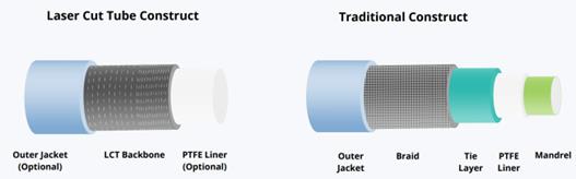
Figure 1: Braid Based vs Lasercut Hypotube Based Catheter Construction
Figure 1: Braid Based vs Lasercut Hypotube Based Catheter Construction
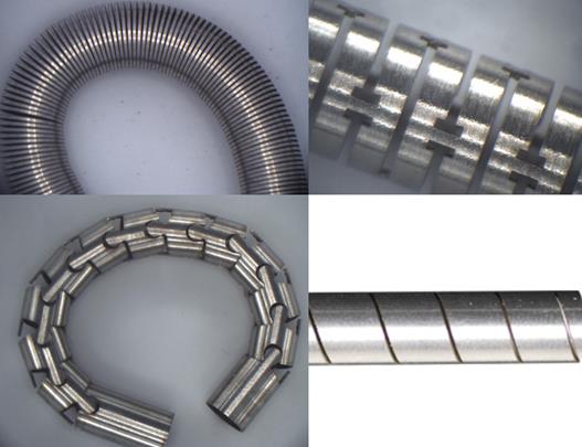
Figure 2: Common Lasercut Patterns
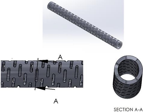
Figure 3: CAD Model- Interrupted Spiral Lasercut Pattern
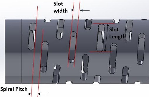
Figure 4: Critical Parameters Definition- Interrupted Spiral Lasercut Pattern
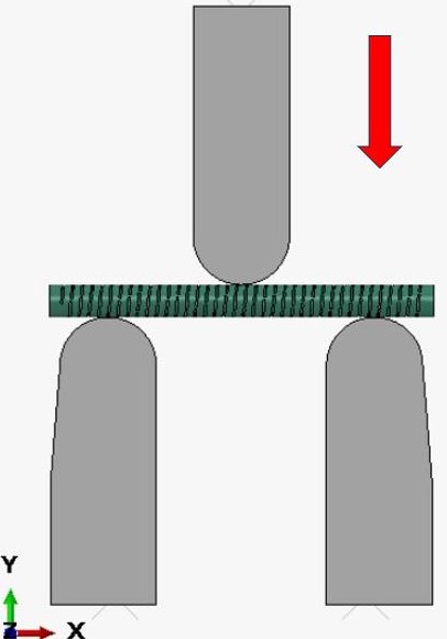
Figure 5: Test Setup-3pt Bend Test
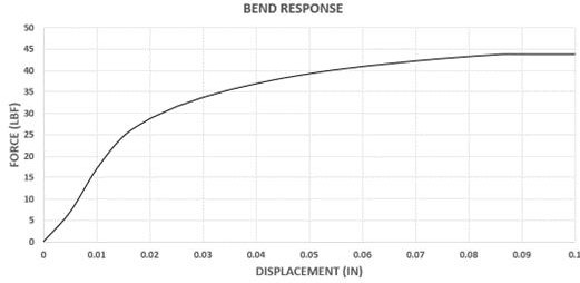
Figure 6: Force vs Displacement Curve- 3Pt Bend Test
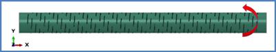
Figure 7: Test Setup-Torsion Test
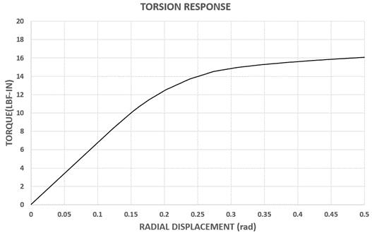
Figure 8: Torque vs Radial Displacement Curve- Torsion Test
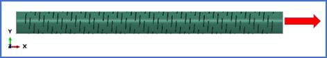
Figure 9:Test Setup-Tensile Test
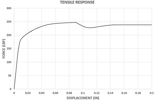
Figure 10: Force vs Displacement Curve- Tensile Test
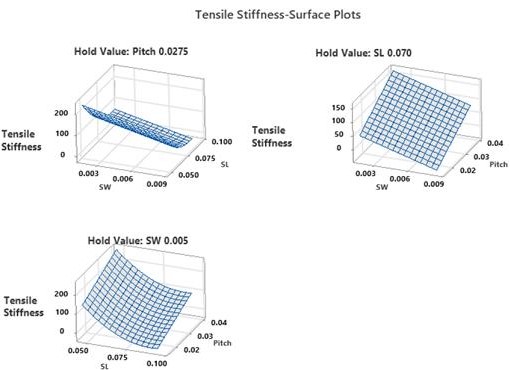
Figure 11: 3D Surface Plots- Tensile Stiffness
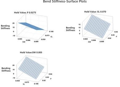
Figure 12: 3D Surface Plots- Bend Stiffness
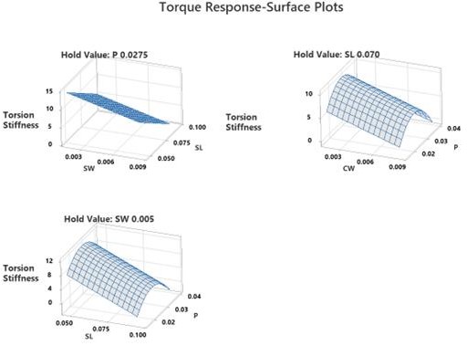
Figure 13: 3D Surface Plots- Torsional Stiffness
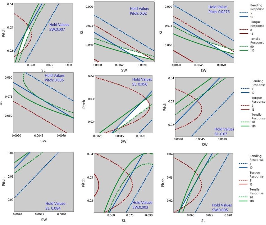
Figure 14: Overlaid Contour Plot Matrix
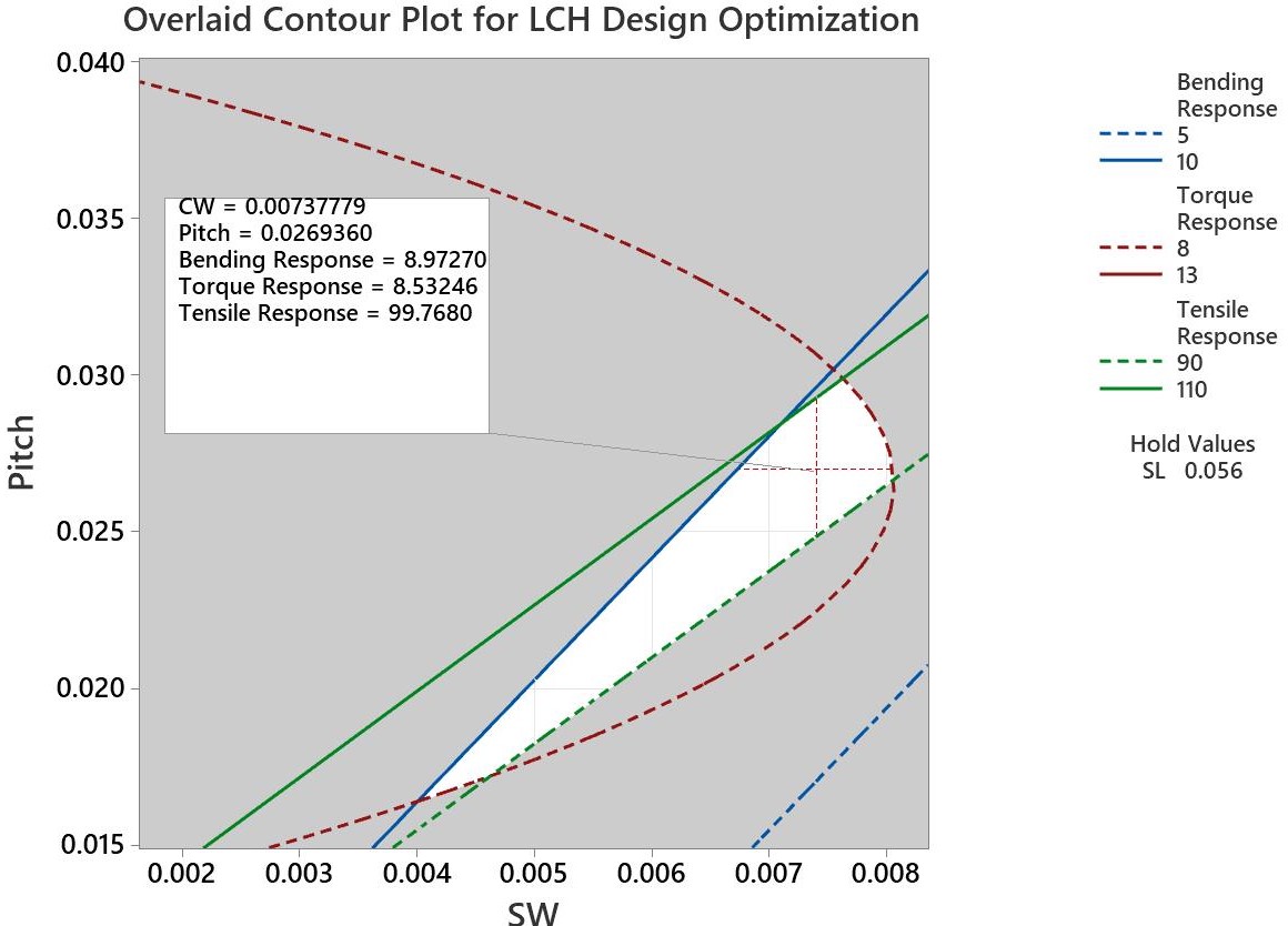
Figure 15: Overlaid Contour Plot- Pitch vs SW
Tables at a glance
Figures at a glance