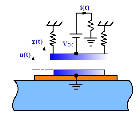
Figure 1 The basic structure and working mechanism of the miniature resonant capacitive sensing unit
Figure 1 The basic structure and working mechanism of the miniature resonant capacitive sensing unit
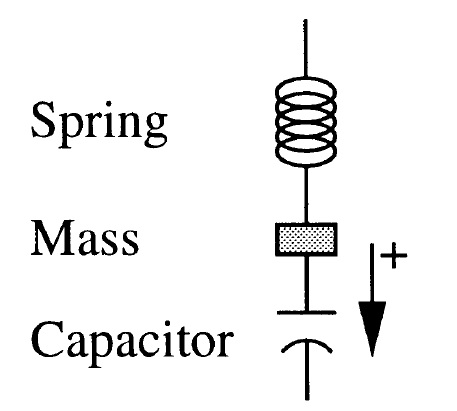
Figure 2 Schematic diagram of a single degree of freedom system
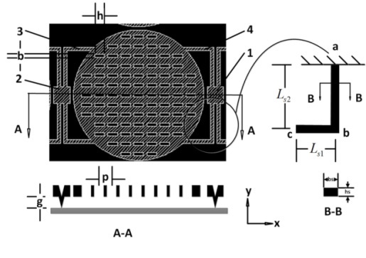
Figure 3 Structure of the out-of-plane sensing unit
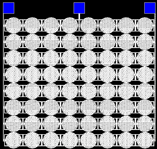
Figure 4 CAD layout of the out-of-plane sensing unit
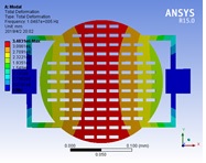
Figure 5 Undamped state of the next-order vibration mode
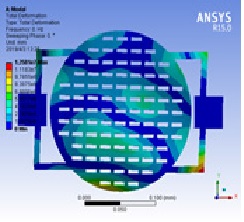
Figure 6 The next-order mode cloud image with damping
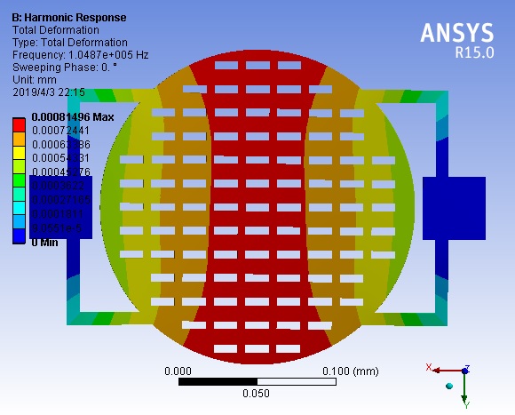
Figure 7Cloud map with damped harmonic response displacement
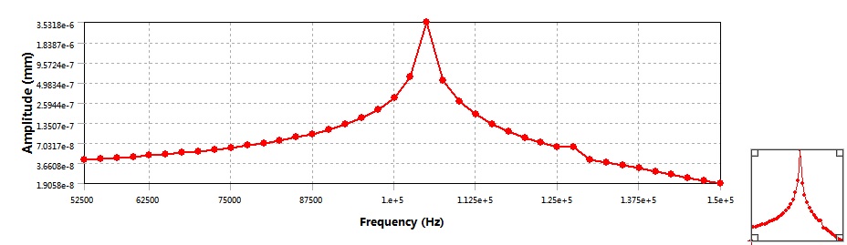
Figure 8 sensing unit response frequency-amplitude curve
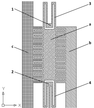
Figure 9 In-plane sensing unit responds in the x-direction
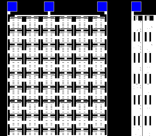
Figure 10 The planar sensing unit responds in the y-direction
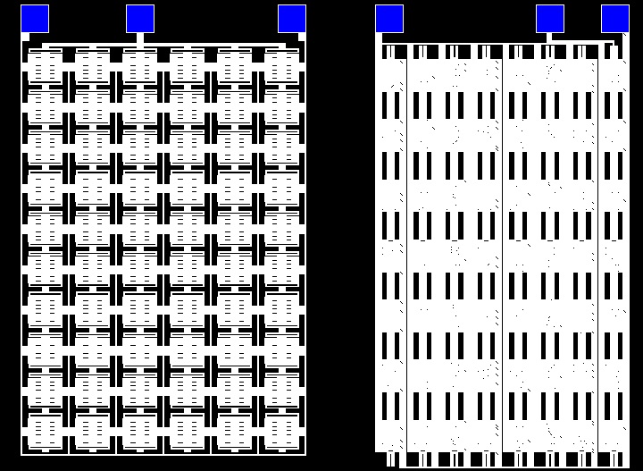
Figure 11 CAD layout of the in-plane sensing unit
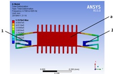
Figure 12 First-order mode modality in the x-direction
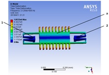
Figure 13First-order mode modality in the z-direction
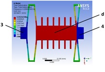
Figure 14 First-order mode modality in the y-direction
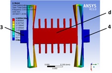
Figure 15 First-order mode modality in the z-direction