Characterization of a Novel Low-Loss Ferroelectric Composite FE - BTV Using Multi-Resonance Anchored Permittivity Extraction
Received Date: December 09, 2025 Accepted Date: January 26, 2026 Published Date: January 31, 2026
doi:10.17303/jnsm.2025.11.103
Citation: Habib Tabelsi, Hafedh Ibrahim Gaha, Hatem Essaidi, Ali Gharsallahi (2025) Characterization of a Novel Low-Loss Ferroelectric Composite FE BTV Using Multi-Resonance Anchored Permittivity Extraction. J Nanotech Smart Mater 11: 1-14
Abstract
This paper presents a robust hybrid methodology for broadband extraction of complex permittivity from vector network analyzer (VNA) measurements in a partially filled rectangular cavity. By anchoring localized ABCD-based numerical inversion to physics-derived resonance points, our approach yields smooth, artifact-free permittivity spectra over wide bandwidths. The method is applied to a novel ferroelectric BaTiO3–V2O5 ceramic composite, denoted FE − BTV, synthesized via solid-state reaction. In a 2.00 mm× 10.0 mm × 23.0 mm cavity, 16 resonances are detected between 8.37 GHz and 13.8 GHz, revealing a monotonically decreasing real permittivity from ε′ = 83.4 to 30.8 and an exceptionally low loss tangent (tan δ < 1.09 × 10⁻⁴), over 180 times lower than that of standard FR-4 substrates. These results confirm the FE − BTV composite as a promising candidate for low-loss microwave applications, including 5G/6G substrates, satellite antennas, and mmWave radomes.
Keywords: Complex permittivity, resonant cavity, vector network analyzer (VNA), ABCD matrix in- version, multi-resonance characterization, low-loss dielectric, S-parameter de-embedding, microwave material characterization, FE − BTV composite.
1. Introduction
Accurate broadband characterization of complex permittivity ε(f) = ε′(f) − jε′′(f) is essential for the design of high-performance microwave and millimeter-wave components in 5G/6G communications, radar, and sensing systems [1]. Conventional techniques such as the Nicolson–Ross–Weir (NRW) method require the test material to completely fill a waveguide or coaxial line, a constraint that is often impractical for high-permittivity, brittle, or custom-shaped samples [2]. Resonant cavity methods, while offering exceptional accuracy and sensitivity, are traditionally limited to discrete frequencies, hindering the reconstruction of continuous dispersion profiles [3].
To bridge this gap, we propose a hybrid methodology that leverages multiple resonances within a partially filled cavity to synthesize a smooth, physically consistent broadband permittivity spectrum. The approach is applied to FE − BTV, a novel ferroelectric composite based on an equimolar solid-state reaction of barium titanate (BaTiO3) and vanadium pentoxide (V2O5). FE − BTV exhibits ultra-low dielectric loss and high permittivity, properties highly desirable for next-generation microwave substrates and passive components [4].
Our approach integrates the analytical rigor of cavity perturbation theory [5] with localized, anchor-guided numerical inversion strategy. Unlike global optimization frameworks that often yield non-unique or unphysical solutions, particularly for low-loss materials [6], our technique enforces thermodynamic consistency by initializing numerical inversion at analytically derived resonance points. This ensures artifact-free, monotonic dispersion across the entire band. The main technical contributions of this work are threefold : first, a hybrid multi-resonance anchoring strategy that links numerical inversion directly to physical resonance structure, ensuring thermodynamic consistency ; second, a robust de-embedding and ABCD-based inversion pipeline that eliminates numerical artifacts commonly observed in broadband S-parameter fitting, especially critical for ultralow-loss materials; and finally an extension of the method to asymmetric two-port measurements by enforcing reciprocity through symmetrization of S21 and S12, thereby enabling accurate characterization of non-ideal or imperfectly aligned samples. The experimental setup employs a custom rectangular cavity (2.00mm × 10.0mm × 23.0mm) interfaced via coaxial connectors. Full two-port S-parameter measurements over 8.00GHz to 14.0GHz reveal pronounced asymmetry (S11≠S22), confirming the need for a generalized, reciprocity-aware inversion framework, precisely the capability our algorithm provides.
2. Theory: Permittivity Extraction
The complex relative permittivity ε(f) = ε′(f) − jε′′(f) quantifies a material’s ability to store and dissipate electromagnetic energy at microwave frequencies. In resonant cavity methods, accurate permittivity extraction relies on a precise link between measurable resonance characteristics and the material’s electromagnetic response.
Consider a rectangular metallic cavity of dimensions a × b × d, where a = 2.00mm (width), b = 23.0mm (height), and d = 10.0mm (length). When operated in the dominant TE101 mode, characterized by one half wave variation along the x- and z-directions and no variation along y (i.e., mode indices m = 1, n = 0, p = 1), the resonant frequency f0 depends only on a and d, and is related to the real part of the permittivity ε′ by [7, 8]:
where c denotes the speed of light in vacuum. The cavity height b does not appear in Eq. (1) because the TE101 mode exhibits no field variation along that dimension (n = 0), a well-established result in cavity electrodynamics [7].
Dielectric loss is captured through the imaginary part ε′′, derived from the loaded quality factor QL, which reflects total energy dissipation in the resonant system. Using the phase response of the transmission coefficient, QL can be approximated as [9, 10]:
where ϕ = ∠S21(f) is the unwrapped phase of the forward transmission parameter. Assuming conductor losses are negligible, a valid assumption given the high conductivity of the copper-alloy cavity walls [8], the dominant loss mechanism is dielectric, and we obtain:
These analytical expressions yield physically grounded estimates of ε′ and ε′′ at discrete resonance frequencies. However, they do not provide a continuous ε(f) profile across the band. While broadband extraction methods based on S-parameter optimization exist [9], they are prone to non-uniqueness and numerical artifacts unless constrained by physical priors. Our approach overcomes this limitation by using the analytical resonance values as anchors for a guided numerical inversion, ensuring both spectral continuity and physical fidelity, as detailed in Section 3.
3. Methodology : Multi-Resonance anchored permittivity extraction
To overcome the limitations of purely analytical or purely numerical permittivity extraction techniques, we introduce a hybrid methodology that synergistically combines discrete resonance physics, grounded in cavity perturbation theory, with localized, constraint-guided numerical inversion. The fixture constitutes a partially FE −BTV-filled rectangular cavity, where the dielectric sample fully occupies the transverse cross-section a × d=2.00mm × 10.0mm and extends over the full height b = 23.0mm. Since the filling factor is unity in the transverse plane, the unperturbed TE101 resonance formula serves as a valid first-order approximation. The workflow comprises three interdependent stages:
1. Resonance detection: Resonant frequencies are identified by locating zero-crossings of the transmission phase ϕ(f) = ∠S21(f) that exhibit high phase slope, specifically, those in the top 10% of |dϕ/df|−1. Sub-grid frequency refinement is achieved via linear interpolation.
2. Analytical anchoring: At each detected resonance f0, the complex permittivity is computed directly from f irst principles using Eq. (1) and Eq. (2). These points serve as physically grounded anchors, free from fitting ambiguity.
Guided ABCD Inversion: From each anchor, ε(f ) is propagated bidirectionally over a 364 MHz neigh- borhood (±182 MHz) using a least-squares fit of a transmission-line ABCD model to the measured S- parameters. Propagation halts at band edges or upon optimization failure, ensuring numerical stability. Overlapping neighborhoods from adjacent resonances naturally merge into a continuous, monotonic profile across 8.00 GHz to 14.0 GHz.
The inversion core relies on the ABCD matrix of a homogeneous dielectric slab of length L=23.0mm:
Where γ = jω√µ0ε0εandZc= µ0/(ε0ε) [8]. This model assumes quasi-TEM propagation and remains valid below the cutoff of higher-order waveguide modes.
Although the measured S-matrix exhibits mild asymmetry, the underlying passive structure is reciprocal. To mitigate measurement-induced asymmetry and improve robustness, we enforce reciprocity by defining a symmetrized transmission coefficient:
The S-parameters are converted to ABCD form using the standard two-port transformation [7]:
A trust-region least-squares optimizer minimizes the residual between the model and measured ABCD matrices by adjusting ε′ and ε′′. The optimizer uses the trust-region-reflective algorithm as implemented in SciPy’s least_squares routine. Convergence is declared when the Euclidean norm of the gradient falls below 1×10⁻⁶ or when the relative change in the parameter vector [ε′,ε′′] is less than 1×10⁻⁵. A maximum of 100 iterations is allowed per frequency point. Initial bounds are set to ε′∈ [10,120] and ε′′ ∈ [10−6, 10−2], consistent with expected dielectric behavior in this frequency range.
These settings ensure stable convergence without overfitting. Each inversion starts from the analytically computed anchor value and uses the solution at frequency fi as the initial guess for fi±1, enforcing smoothness and suppressing non-physical local minima. By confining inversion to narrow bands centered on resonances, the method avoids the ill-conditioning that plagues global fitting. The resulting ε(f ) is thus both physically consistent and numerically stable. This multi-resonance anchoring paradigm represents a significant advance over unguided optimization frameworks, which often produce spurious oscillations or non-monotonic behavior in low-loss materials [11, 12].
4 Material Synthesis and Characterization
4.1 BaTiO3V2O5 Composite Preparation: (FE − BTV)
To prepare our ferroelectric BaTiO3V2O5 composite, a solid-state reaction synthesis method was applied to ensure optimal atomic positioning and superior electrical properties across various frequency ranges (8 GHz, 14 GHz). The process used high-purity precursors, including Ba(NO3)2 and TiO2 powders with purity greater than 99%, along with V2O5 as an agent to improve the electrical performance of the composite [13]. Initially, BaTiO3 and V2O5 powders were mixed in an equimolar ratio and manually homogenized for one hour in an agate mortar, with regular intervals to prevent particulate agglomeration. The mixture then underwent a biphasic heat treatment consisting of calcination at 350oC for 2 hours to remove volatile compounds, followed by high- temperature synthesis at 1000oC for 3 hours to form the composite. After synthesis, the powder was shaped using a 13 mm diameter die and compacted under a pressure of 10 bars, then sintered at 1100oC to achieve granular coalescence and densification. Finally, a conductive silver lacquer was applied to the surface, and copper wire electrodes were fixed to complete the preparation. The structural analysis of the powder obtained was carried out using an X-ray Philips X-pert machine with a Cu source (λCu = 1.5406 Å), a voltage of 45 kV, and a current of 40 mA. Phase identification was performed using PANalytical Highscore v4.9 software. The XRD model obtained for the BaTiO3V2O5 composite was compared to the individual XRD patterns of BaTiO3 and V2O5, as shown in Figure 2.
The BaTiO3V2O5 composite sample has peaks at clearly defined positions. Peaks of crystallographic planes such as (200), (010), (001), (101), (310), (100), (020), (411), (600), (201), (012), (211), (421), (402), (711), and (602) are attributed to BaTiO3, while other peaks such as (200), (010), (101), (310), (020), (411), (600), (012), (402), (701), (711), and (602) can be attributed to V2O5. Peaks at angles of 2θ = 8.02◦, 47.80◦, and 48.84◦ are unknown and can probably be attributed to binary phases between BaTiO3 and V2O5. The presence of (hkl) planes from both BaTiO3 and V2O5 in the composite confirms the coexistence of both compounds (Figure 2) [14, 15].
4.2 Morphological Analysis by Atomic Force Microscopy (AFM)
The measured roughness values are consistent with the requirements for RF applications up to 1020 GHz, in accordance with established literature [16]. To evaluate the impact of sintering on the surface topography of the FE-BTV composite, the powder was compacted under a pressure of 10 bars, and the resulting pellet was characterized by atomic force microscopy (AFM). Figure 3 shows 2D AFM micrographs acquired over a scan area of (1.7 µm 1.4 µm). The AFM Image analysis reveals a relatively homogeneous and densely packed particle distribution. The microstructures appear partially interconnected, resulting in a moderately rough surface morphology. Additionally, an irregular arrangement of larger agglomerates is observed, along with clearly defined grain boundaries or interfaces between adjacent domains. The root mean square surface roughness (RMS) was measured to be approximately 95 nm and arithmetic average of surface roughness profile (AA) is around 77nm.
4.3 Results and Discussion
Figure 4 summarize the measurement experimentation and Figure 5 shows S11 and S21 across 8.00 GHz to 14.0 GHz, with 16 resonances marked by red dashed lines. The low |S11| away from resonance indicates good impedance matching.
Table 2 summarizes permittivity values at each resonance. The monotonic decrease of ε′ (83.4 → 30.8) and ultra-low tan δ < 1.09 × 10 −4—over 180× lower than FR-4 [17, 18], confirm FE-BTV as a superior low-loss material. The exceptionally low loss tangent (tan δ < 1.09 10−4) is attributed not only to the high material density but also to the incorporation of V2O5.
Vanadium pentoxide is known to suppress oxygen vacancy formation in perovskite lattices by acting as an acceptor dopant or by forming secondary phases that immobilize mobile defects [14, 13, 15]. In BaTiO3–V2O5 composites, V5+ ions likely segregate at grain boundaries, reducing ionic conduction and dipolar relaxation losses. Additionally, the formation of Ba–V–O interfacial phases (evidenced by unindexed XRD peaks at 2θ 8.02◦, 47.80◦, and 48.84◦) may passivate defect states, further lowering ε′′. Figure 6 confirms smooth, monotonic dispersion. Figures 7 and 8 illustrate excellent agreement between analytical anchors and propagated ε(f ), validating our method’s stability and accuracy.
5. Conclusion
We have presented a robust hybrid methodology for continuous broadband extraction of complex permittivity from VNA measurements in a partially filled cavity. By anchoring localized ABCD-based numerical inversion to physically derived resonance points, the approach eliminates instability and non-uniqueness associated with unguided optimization while preserving high spectral fidelity. Applied to the ferroelectric composite FE - BTV (BaTiO3 –V2O5), the method reveals an exceptionally low loss tangent (tan δ < 1.1 × 10⁻⁴) and a smooth, monotonically decreasing permittivity from ε′ = 83.4 to 30.8 over 8.00 GHz to 14.0 GHz, more than two orders of magnitude lower loss than standard FR-4 substrates. These properties confirm FE-BTV as a highly promising candidate for next-generation microwave applications, including 5G/6G substrates, satellite communication antennas, and mmWave radomes. Future work will extend this framework to temperature-dependent characterization and rigorous uncertainty quantification through co-simulation with full-wave electromagnetic solvers, while also incorporating scanning electron microscopy (SEM) and energy-dispersive X-ray spectroscopy (EDS) mapping to directly correlate microstructural homogeneity, phase distribution, and porosity with the observed ultra-low dielectric loss.
- Baker-Jarvis J, Janezic MD, Grosvenor JH (2020) “Dielectric and conductor-loss characterization,” Tech. Rep. NIST Technical Note 2109. National Institute of Standards and Technology.
- Weir WB (1974) “Automatic measurement of complex dielectric constant and permeability at microwave frequencies,” Proceedings of the IEEE. 62: 33–36.
- Gupta S, Zhang Y, Chen LF (2021) “High-Q resonant cavity for material characterization,” IEEE Transactions on Microwave Theory and Techniques. 69: 2567-75.
- Zhang Y, Wang H, Liu B (2023) “Low-loss ceramics for 6g applications,” Materials Today. 62: 105-13.
- Chen LF, Ong CK, Neo CP, Varadan VK (2018) Microwave Materials Characterization. SciTech Publishing.
- Kůrka P, Havelka D, Cifra M (2025) “Broadband extraction of sample permittivity from microwave planar trans- mission lines,” IEEE Transactions on Microwave Theory and Techniques. 73: 6707-18.
- Pozar DM (2021) Microwave Engineering. Hoboken, NJ: Wiley. 5th ed.
- Collin RE (2020) Foundations for Microwave Engineering. Wiley-IEEE Press.
- Janezic MD, Baker-Jarvis J (2019) “Algorithms for permittivity extraction from S-parameter measurements,” IEEE Transactions on Microwave Theory and Techniques. 67: 1025-32.
- National Institute of Standards and Technology (2022) “Permittivity measurement standards,” Tech. Rep. NIST Special Publication 1256, National Institute of Standards and Technology.
- Kozlov A, Petrov D, Ivanov M (2021) “ABCD-based inversion for thin-film dielectric characterization,” Review of Scientific Instruments. 92: 084701.
- Ghasemi A, Abdolali A (2022) “Multi-resonance inversion for dielectric characterization,” Journal of Applied Physics. 131: 044101.
- Silva R, Oliveira R, Silva M, Sombra A (2019) “Effect of v2o5 addition on the structural and electrical properties of cotio3,” Composites Part B: Engineering. 176: 107286.
- Chandran R, Sreekala C, Menon SKJMTP (2020) “Batio3/v2o5 composite based cylindrical dielectric resonator antenna for x-band applications,” Materials Today: Proceedings. 33:1367-70.
- Morad I, Harby AE, Ayoub M, Ali HE, El-Desoky MJJoEM (2023) “The role of nanocrystallization for the enhancement of structural, electrical, and transport properties of batio3-v2o5-pbo glasses,” Journal of Electronic Materials. 52: 7171-83.
- Almeshehe M, Murad N, Rahim M, Ayop O, Samsuri N, et al. (2022) “Surface roughness impact on the performance of the 3d metal printed waveguide coupler at millimeterwave band,” Engineering Science and Technology, an International Journal. 35: 101129.
- Rogers Corporation (2023) “High-frequency material selection guide,” tech. rep.
- Szostak K, Słobodzian P (2018) “Broadband dielectric measurement of pcb and substrate materials by means of a microstrip line of adjustable width,” IEEE-letter / Conference or Journal (see note).
FIGURE 1
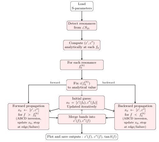
Figure 1: Flowchart of the multi-resonance anchored permittivity extraction algorithm.
FIGURE 2
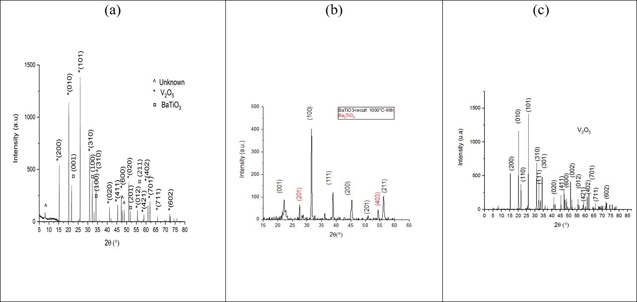
Figure 2: XRD comparison of composite (a) BaTiO3V2O5 with (b) BaTiO3 and (c) V2O5.
FIGURE 3
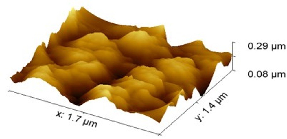
Figure 3: Two-dimensional AFM image (1.7 µm × 1.4 µm) of the BaTiO3/V2O5 composite.
FIGURE 4
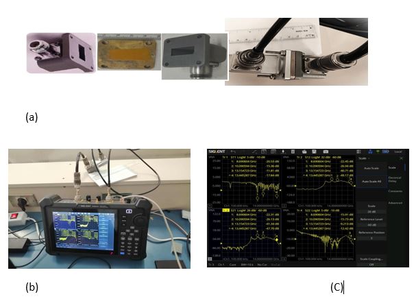
FIGURE 5
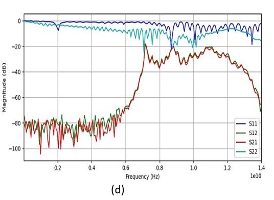
Figure 4: Experimentation and S matrix measurement : (a) composite filling (b) measurement on VNA- SHN914A (c): S viewing (d) 4 complex Sij
FIGURE 6
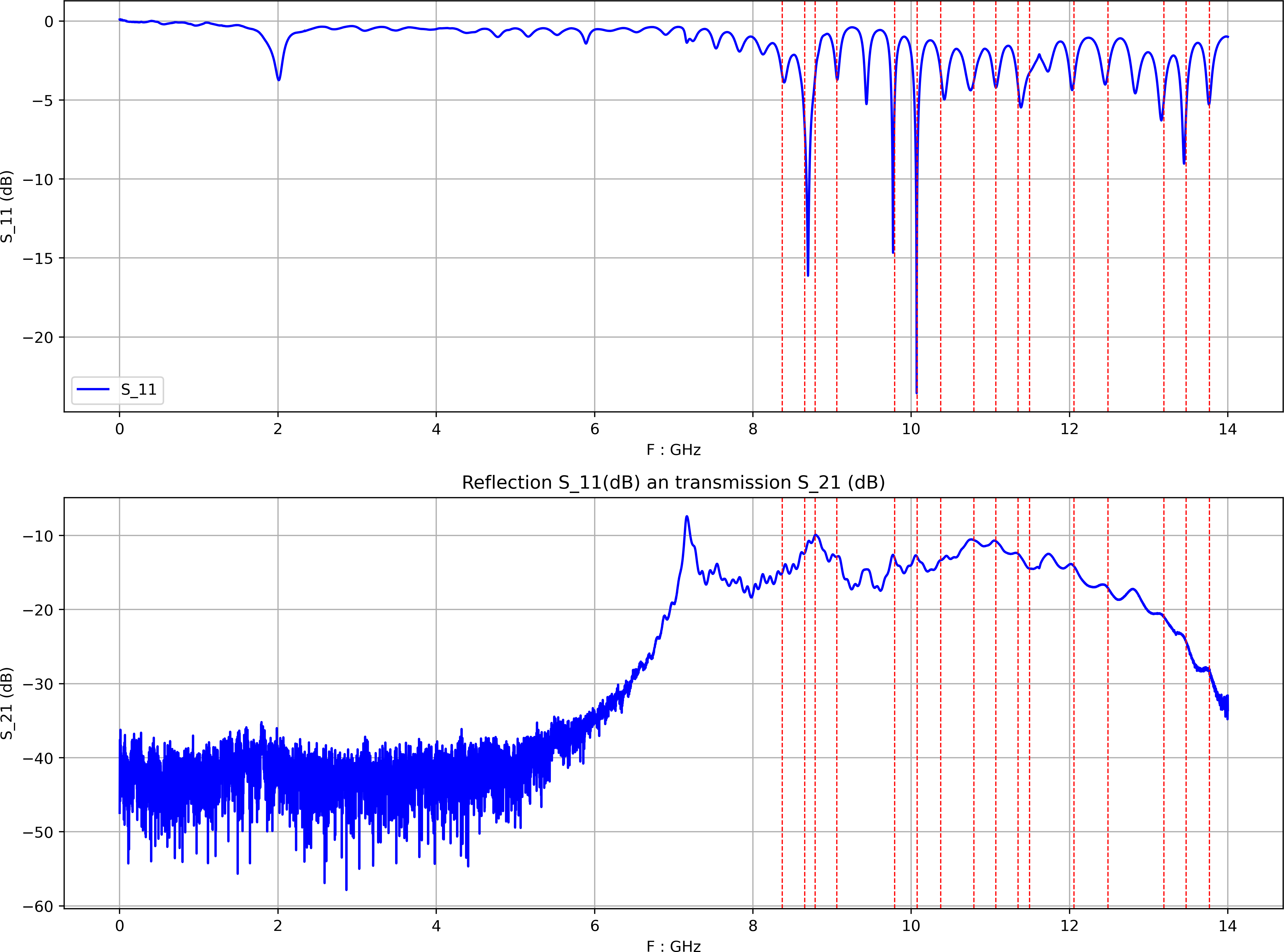
Figure 5: Reflection S11 and transmission S21 in dB. Red dashed lines mark the 16 detected resonances.
FIGURE 7
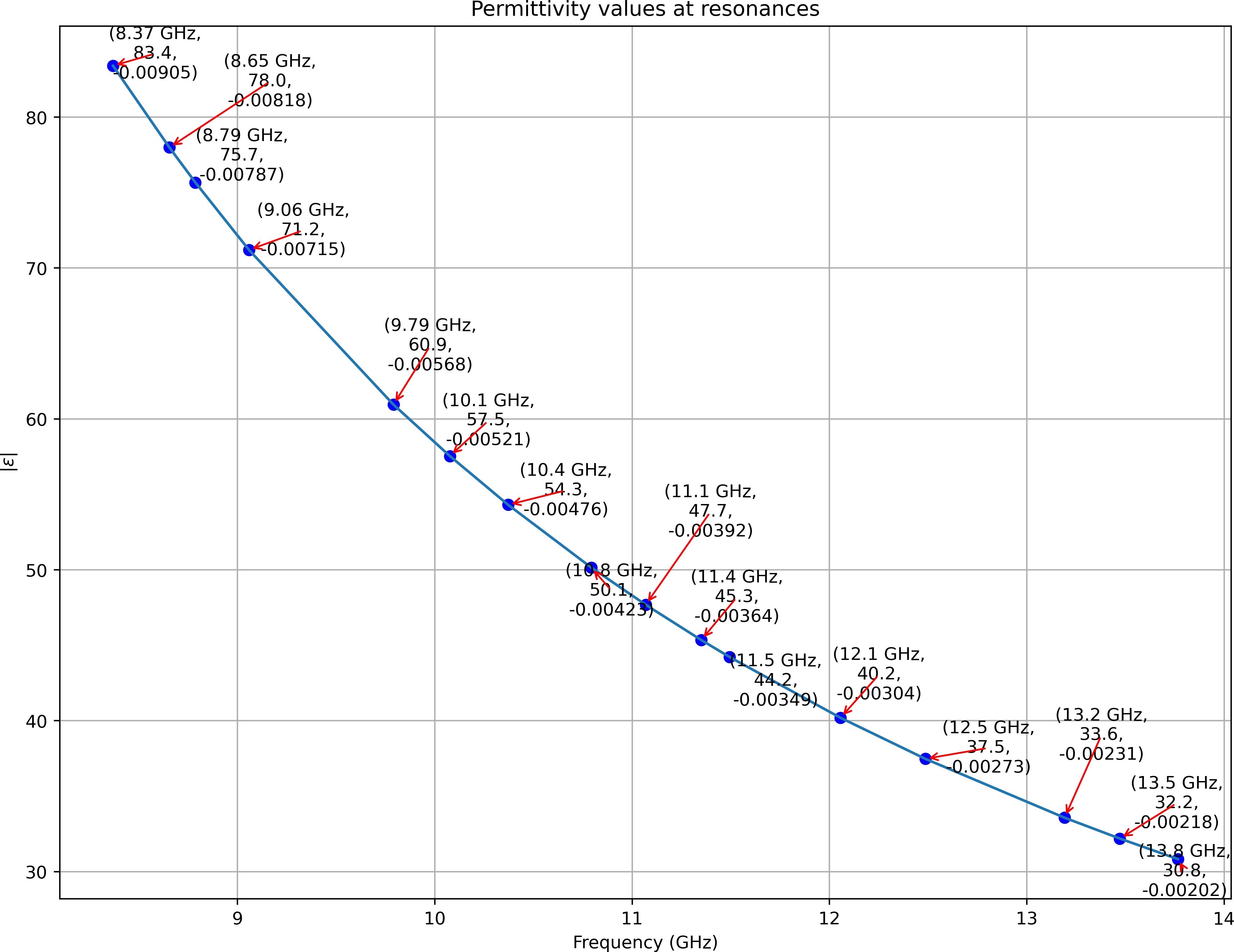
Figure 6: Permittivity magnitude at 16 resonances.
FIGURE 8
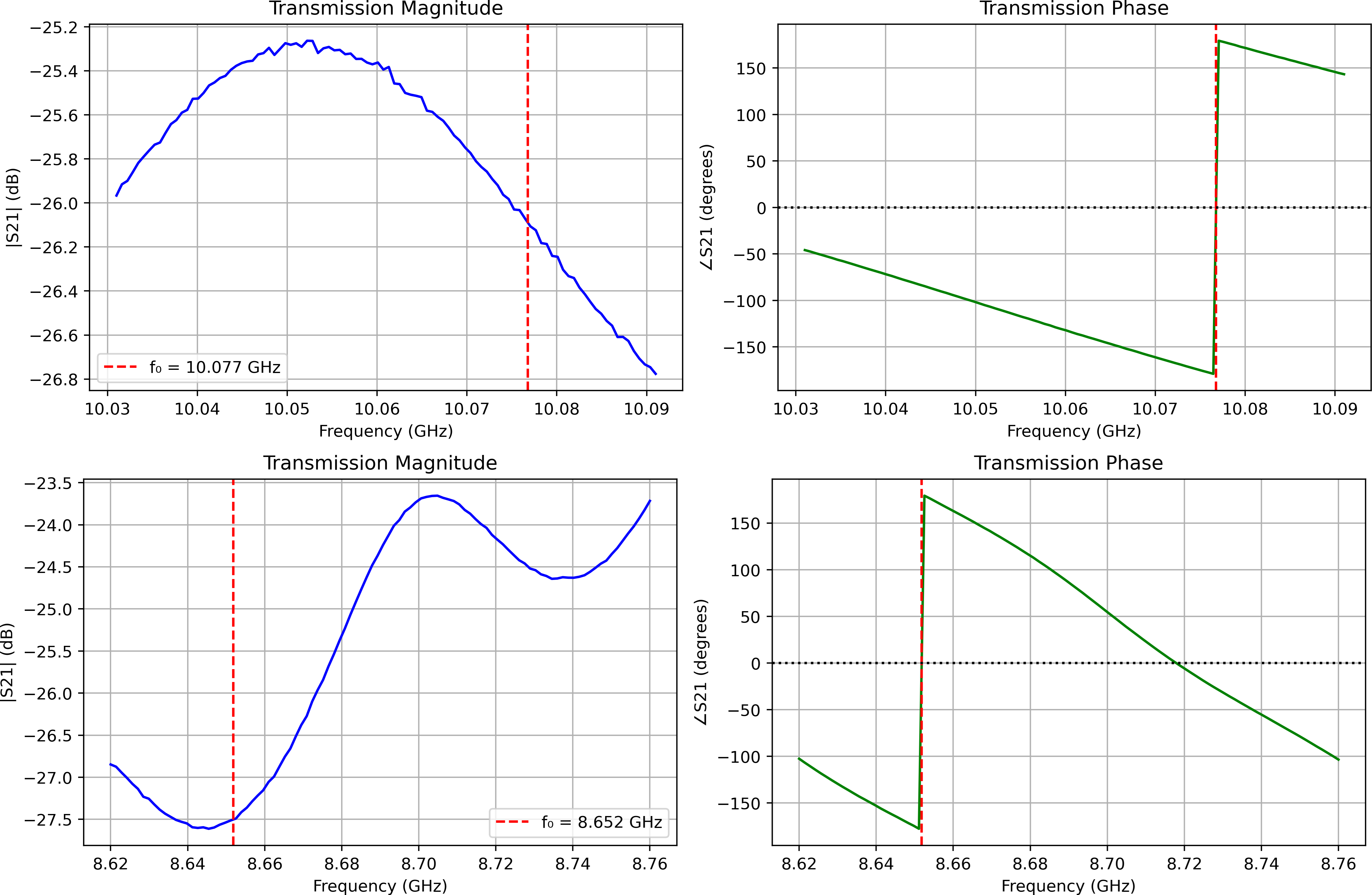
Figure 7: Permittivity profile around 8.65 and 10.07 GHz resonances.
FIGURE 9
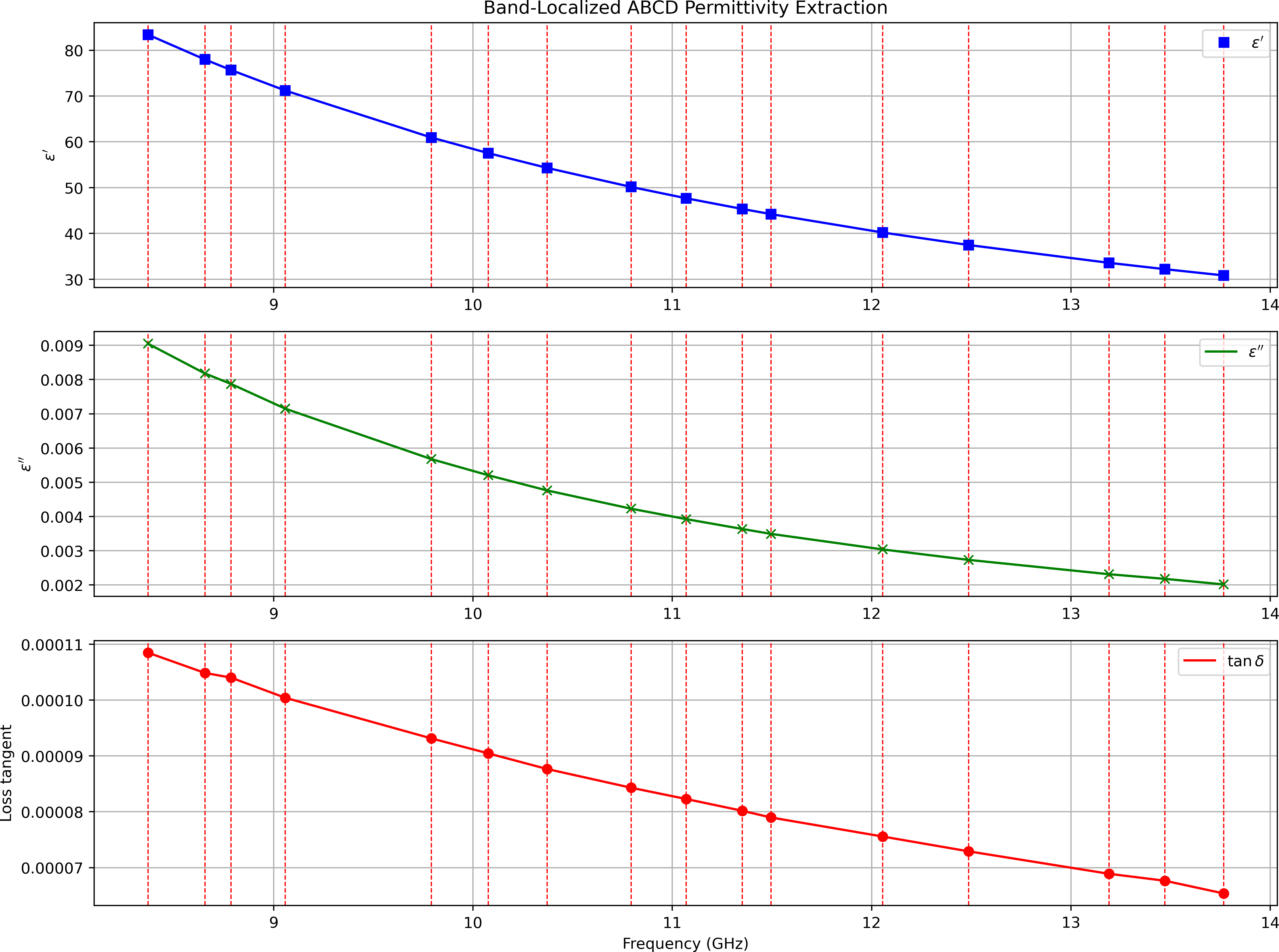
Figure 8: Full-band complex permittivity of FE − BTV over 8.00 GHz to 14.0 GHz.
Tables at a glance
Figures at a glance