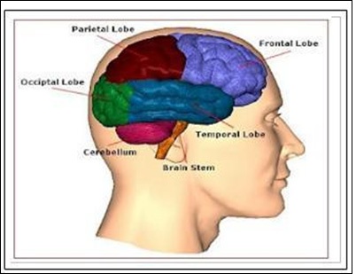
Figure 1 Brain structure
Figure 1 Brain structure
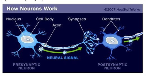
Figure 2 Neural network (between 2 neurons).
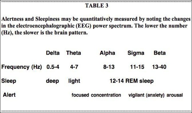
Figure 3Types of brain-waves
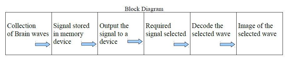
Figure 4Block diagram: Further processing of Collected Brain Signals.
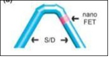
Figure 5 [9] Kinked nanowire probe. Pink: nanoFET, blue: nanoscale source, drain electrodes.
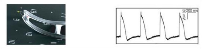
Figure 6 Left :- a 3D free-standing kinked nanowire FET bent probe. Yellow arrow (at the tip of V nanowire) marks the nanoscale FET. Scale bar: 5 micrometer. Right:- Steady-state intracellular recording [9].
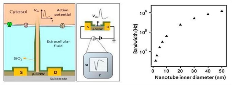
Figure 7a) BIT-FET nanoprobe b) Calculated bandwidth of the device vs nanotube inner diameter for a fixed nanotube length of 1.5 ìm [9].
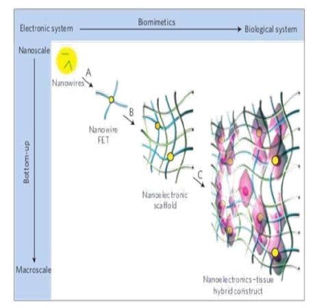
Figure 8Coneptual steps for merging nanoelectronics with artificial tissues seamlessly in 3D [11].
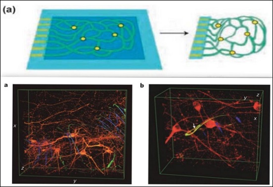
Figure 9Top: Reticular nanoES: a) Device fabrication schematics for reticular nanoES. Light blue: silicon oxide substrates; blue: nickel sacrificial layers; green: nanoES; yellow dots: individual nanowire FETs. Bottom:3D tissue hybrid/ nanoelectronics:3D reconstructed confocal images of rat hippocampal neurons after a two-week culture on a reticular nanoES. a) Red: neuronal â-tubulin; yellow: epoxy ribbons. The metal interconnects are false coloured in blue. b) The white arrow highlights a neurite passing through a ring-like structure supporting a nanowire FET[11].
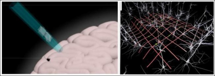
Figure 10Left:- The highly flexible nano-electronic network is delivered into the brain by either injecting through a needle inserted into the brain (shown) or inserting supported on a removable or biodegradable rigid support probe. Right: - Depiction of the nanoelectronic network merged with a brain neural network after implantation in a minimally-invasive manner. The green dots indicate positions of the nanoelectronic devices, and the red lines correspond to both encapsulated electronic interconnects and structural elements [12].
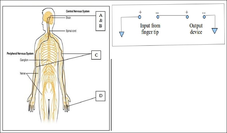
Figure 11Left:- A&B – 3D electonic tissue (embedded with nanoFET sensors & memory element) placed inside brain. C – CNWs carry signal from sensor to finger tips. D – Recorder probes placed on finger tips, from where signals are sent to an output device. Right:-Circiut diagram: showing how brain signals are collected outside the human body. Brain signals from the recorder probes (on finger tips) sent to an output device via an outside circuitry.
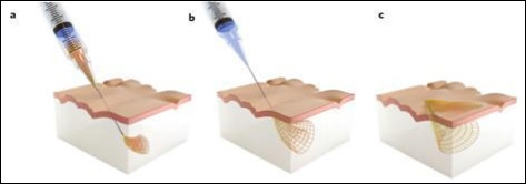
Figure 12A rolled up 3D electronic mesh that is injected into a mouse brain. Once there, it unfolds and melds with the brain tissue [13].