Design and Fabrication of 3D Electrospun Nanofibrous Polyurethane Layers as Potential Application in Pressure Treatment Clothing
Received Date: November 18, 2022 Accepted Date: January 18, 2023 Published Date: January 21, 2023
doi: 10.17303/jnsm.2022.8.105
Citation: Kimia Davoudi, Ali Akbar Gharehaghaji (2023) Design and Fabrication of 3D Electrospun Nanofibrous Polyurethane Layers as Potential Application in Pressure Treatment Clothing. J Nanotech Smart Mater 8: 1-16
Abstract
Clothing in treatment subjects, including different orthoses and pressure garments, has been used for many years because ofvarious issues. The importance of their performance resulted in other research and progressive achievements in producing different kinds of them. Electrospun polyurethane (PU) nonwoven has shown good potential for medical applications due to flexibility, porosity, and mechanical properties. In this study, 3D polyurethane nanofibrous layers (cylindrical seamless tubes) were fabricated by the electrospinning process. After that, different properties, including air and water vapor permeability, indentation, compression, and tensile behavior, were examined. Laplace law was used for calculating the generated pressure on the circular and oval cross-sectional body limbs. Fabricated layers showed high flexibility. The results showed that with increasing the electrospinning duration, the weight and thickness and consequently the amount of force required for indentation and compression were increased, but the amount of air and water vapor permeability didn’t have a pronounced change. The amount of pressure generated by the fabricated layer can be controlled by changing the cylindrical seamless layer's circumference and consequently changing the amount of needed strain. This study indicated that the 3D electrospun PU layers have good applicability potential for consideration as treatment clothing or part of that in the field of pressure garments and orthoses.
Keywords: Treatment Clothing; Polyurethane; Electrospinning; Nanofibrous Layer; 3D Shape Memory; Comfort; Laplace Law.
Introduction
The applicability of clothing as orthoses and pressure garments has been investigated for many years because of their enormous usage in different medical treatments or sports and the importance of their performance. Research has resulted in progressive achievements in producing and examining different kinds of orthoses and pressure garments used for different parts of body limbs. As a result, several types of orthoses and pressure garments with other methods and materials are produced depending on the body parts and requirements [1-12].
There have been different researches in the field of orthoses production, including comfort, limitation of movement, the amount of acting forces, and interface pressures [1-3] [5,13]. On the other hand, different parameters have been investigated about pressure garments, such as the pressure generated on the body and comfort properties, including air and water vapor permeability. Several types of research predicted and measured the amount of exerted pressure on the body by pressure garments. As investigations showed, several parameters can influence the exerted pressure. However, not only the characteristics of the garment, such as circumference, reduction factor, tensile behavior, tension, and elasticity can affect the amount of generated pressure on the body; but also, properties of the body part including shape and size, position, limb circumference, and curvature are important. Various ranges of pressure can be generated by changing these parameters [7-12,14].
Electrospun fibers have been considered valuable materials for numerous sports clothing, medical, and biomedical applications due to their special characteristics such as high surface area, porosity, and mechanical properties [15-22]. Electrospinning is one of the most valuable and straightforward methods that has been under focus in the past decades because of its potential for producing fibers with nano and micro diameters from a polymer solution or melt by applying electrostatic forces. To date, various materials including synthetic and natural polymers or a blend of them, have been successfully electrospun into nano-microfibers. The other attractive advantage of electrospinning relies on the fact that the structure and characteristics of electrospun polymeric nanomicro fibers can be controlled by the processing parameters [16-18, 23-26].
Polyurethane (PU) is one of the polymers that has been successfully electrospun in solution form. Polyurethane solution electrospinning is mainly carried out by different amounts of DMF (Dimethylformamide) and THF (Tetrahydrofuran) or a mixture of DMF/THF as solvents with different PU content [20, 25, 27-31].
Some research works reported that 10, 12, and 13 wt% concentrations of polyurethane with the presence of both DMF and THF as solvents were successfully electrospun [21, 27, 29, 32]. Lakshman et al. [20] reported that 12 wt% of PU in THF was optimized for producing nanofibers.
The electrospun PU nonwoven characteristics like flexibility, porosity, and mechanical properties make it a good candidate for different applications; also, electrospun PU and PU blends have shown good potential such as scaolds for bone tissue engineering, artificial blood vessels, protective clothing applications, and wound dressing, [21, 22, 27, 28]. Shape memory is the other important polyurethane property that makes it more useful and applicable and reported works had introduced PU and PU composites as suitable shape memory materials [29, 33, 34]. PU has also been studied as orthotic material and for producing orthosis even in the field of 3D printing technologies [5,35].
In this study, the electrospinning method fabricated 3D nanofibrous polyurethane layers (cylindrical seamless tubes).Their comfort and mechanical properties were examined. The amount of generated pressure on the circular oval cross-sections was calculated by the Laplace law to study the potential application as treatment clothing. Hence, this work aims at assessing the breathability (air and water vapor permeability) and mechanical properties such as compression, indentation, and tensile behavior of the fabricated layer. The electrospun polyurethane layer has the advantages of lightweight, breathability, and flexibility, which are of prime importance for comfort. The continuum structure of the electrospun layer can help the uniform distribution of pressure generated on the body.
Moreover, shape retention and force resistance of the electrospun polyurethane layer can be an excellent advantage for protecting the body and increasing the durability of the clothing. As a result, the 3D electrospun polyurethane layer can be a good candidate as treatment clothing or part of that in the field of pressure garments and orthoses. This subject has not been on focus in previously reported works.
Experimental
Electrospinning process
PU solution was supplied through a 1 ml syringe which was fixed on the syringe pump and then the solution was electrospun by the flow rate of 1.15 ml/h, using 20 kV of voltage. The distance between the nozzle and the aluminum collector was fixed to be 15 cm, and the rotating speed of the collector was set at 70 rpm.
The aluminum surface covered the drum with a 5cm diameter and can be entirely uncovered for picking up the 3D shape samples as a seamless cylindrical tube. The schematic setup of electrospinning is shown in Figure 1.
Surface Morphology Characterization
The morphology of PU electrospun layers was studied by scanning electron microscopy (SEM), (model: XL30; Philips, USA) to determine the mean diameter and layer porosity. For this purpose, 50 fibers out of 5 SEM JScholar Publishers J Nanotech Smart Mater 2022 | Vol 8: 105 images were examined. the diameter of fibers was measured by ImageJ software, and the layer porosity was determined by MATLAB image processing for the thickest layer.
Air permeability
The air permeability of each sample was determined by the SDL air permeability tester (Shirley Developments Limited, UK) for five circular areas (5cm2) of each sample type and the air pressure difference between the under and top of the layer was set at 100 Pa. the amount of air permeability (ml/s.cm2) is measured according to the amount of air that passes through the layer.
Water vapor permeability
The water vapor permeability of each sample was determined by measuring the amount of vaporized water according to the cup method. For this purpose, 10 cc distilled water was put into the cup (with a diameter of 1.5 cm), and the sample was fixed on the top of the cup; 3 cups were prepared for each sample. These samples were kept at room temperature for 72 h, and this time duration was for comparing the results of different samples at stable conditions. Each cup with the mounted sample was weighed before and after this time duration, and the amount of weight loss was measured, indicating the amount of vaporized water.
Compression behavior
The amount of required load for compressive deformation of each prepared sample was measured by loading a disk with 80 g weight and 10 cm diameter. Compression of samples was carried out by the so-called disk and using the tensile tester (Instron, model: 5566; USA). The pressure loading speed was 1 cm/min, and the pressure compressing height was set to 3 cm. The disk compressed the sample at 3 cm height and then returned to its primary state. For measuring this property, 5 various zones of each sample were tested at room temperature (Figure 2).
Indentation depth
Resistance to the indentation force of each prepared sample was measured with the tensile tester (Instron, model: 5566; USA) at room temperature. For this purpose, a circular area of the layer with a 1.5 cm diameter was mounted and fixed on a frame that was designed for this test. After fixing the sample, a 3 mm diameter spherical indenter exerted pressure on the specimen through a 12 mm indentation depth and then returned to its primary position. The crosshead speed was 5 mm/min, and 10 points of each sample were tested (Figure 3).
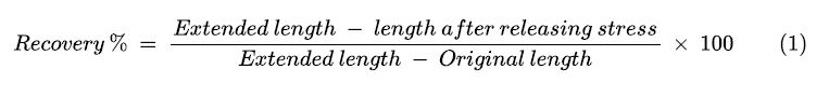
The tensile tester (Instron, model: 5566; USA) was used to measure elastic recovery. For this purpose, the fabricated layer was stretched to 100% of its primary length, and then the tensile tester clamp was returned to its primary level. This cycle was repeated 5 times at room temperature.The gauge length of the sample was 7.5 cm, and the crosshead speed was 200 mm/min throughout the experiments.
The amount of recovery was calculated according to equation (1) [22]:
Calculating the generated pressure by the Laplace law
In this study, the Laplace law is used for calculating the amount of generated pressure. For this purpose, the tensile stretch, as told above, is exerted on the layer for 6 cycles. So, the average tension of the 6 cycles at 25%,50%,75%, and 100% of strain was calculated. Then the modified Laplace law is used for calculating the generated pressure on the circular and oval (elliptic) cross-sections.
Laplace law (equation (2)), and its modified equations, have been used to predict the interface pressure between the layer and the body [7, 10, 11, 14]:
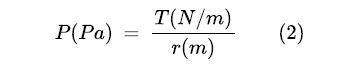
Where P is exerted internal pressure, T is the tension of the layer, r is the radius of curvature.
Equations (3) and (4) show modified Laplace law for the circular cross-section:
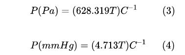
and as mmHg is the common unit for the pressure, the equation is modified to calculate the amount of generated pressure in mmHg:.
where C is the circular circumference (cm) [10, 11].
On the other hand, generated pressure at any points of oval cross-sectional body limbs, which have a cross-section like an ellipse, is different depending on the radius of curvature at that point. For calculating the pressure at various points, the radius of curvature at that point can be replaced in the Laplace law [14]. As the radius of the curvature at any point of an ellipse is calculated by equation (5), the Laplace law is modified as equation (6):
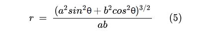
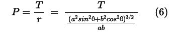
Where a is the major axis of the ellipse and b is the short axis of the ellipse.
The difference in cross-sections is observable in Figure 4.
Results and Discussion
3D polyurethane nanofibrous layers (cylindrical seamless tubes with 5 cm diameter) were produced with weights of 0.0085, 0.0118, 0.0171 g/cm^2 and different thicknesses according to different electrospinning duration (Table 1). As table 1 shows, increasing the electrospinning time duration resulted in increasing the layers' thickness, which is because of the ensemble of fibers mass during the time. In conclusion, these layers were thin and lightweight, and these specifications, as a clothing material, lead to ease of movement and can be more comfortable. As a result, these layers can be useful for use as clothing.
Scanning electron microscope (SEM) images demonstrated that electrospun fibers are successfully formed without beads. Also, the PU electrospun layers have pores with different diameters, as shown in Figure 5. These results are similar to the findings of Han et al. [29] and Gorji et al. [27].
The average diameter of fibers was measured to be 618.8 nm, and the porosity was about 26% for the thickest layer (samples which were electrospun for 8 hrs.).
SEM micrographs indicated that these samples were porous and expected to possess high breathability, which is very important for electrospun layers in clothing applications. To assess the layers’ breathability, air permeability and water vapor permeability of layers were examined, and the results are brought in Table 2.
As the results show, increasing the thickness of layers has a small decreasing effect on air and water vapor permeability. Analyzing the results by SPSS (ANOVA - one way with 95% confidence level) for air and water vapor permeability showed no significant difference between the air permeability of samples. Also, there was no significant difference between the water vapor permeability of the samples. SEM images show that the electrospun layers contain pores with different diameters and distributions that can facilitate the transfer of air and vapor flow through them; hence, the thickness of layers does not have a significant influence. Breathability plays an essential role in clothing comfort, and air and vapor permeability are crucial tests in assessing of layers These PU electrospun layers showed breathability, which was independent of their thickness.
Also, in the work reported by Gorji et al. [27], increasing the thickness of electrospun layers led to a decrease in the amount of air permeability until a specific time duration of electrospinning. After that, the effect of electrospinning time duration and subsequently the effect of layer thickness on the air permeability was reduced.
In addition, water vapor permeability was unchanged in their work, and the thickness of the webs didn’t influence the amount of water vapor permeability [27].
The amount of required force for compression and indentation of these layers was examined, and the results are brought in Table 3.
IAs Table 3 demonstrates, the required force for compression and indentation of these layers was increased by increasing the thickness; these were more pronounced in sample C with the highest electrospinning duration. Tearing happened after inducing pressure in some types of A and B samples due to lower thickness. These results were further assessed by SPSS (ANOVA - one way with a 95% confidence level). The results confirmed that increasing thickness led to an increase in the required force for compression and indentation. Figure 6 and Figure 7 show the effect of electrospinning duration (layer thickness) on the required force for indentation and compression respectively.
SEM images showed that fibers in these layers were connected by bonding and crossing sites. In other words, cohesion and adhesion are initiated between the fibers, so increasing the thickness leads to increased connection sites between fibers which in turn causes higher resistant force build-up against the load. It can be deduced that increasing the mass of fibers in the layer leads to increased connection sites between fibers. It means thicker layers showed more resistance against the force and compressive deformation, and it can be seen especially in sample C. In this sample, the mass of fibers ensemble with interconnected sites is more than the other samples, and these sites could build up a high resistance against compressive forces. Force resisting and shape retention of thicker layers were several times more than that of thin layers, and in conclusion, the thickest layer showed better results for saving its shape.
Han et al. also reported in their research that increasing the thickness of electrospun PU nanofibrous layers led to an increase in shape retention [29].
Overall, shape retention and force resisting can positively influence the applicability of the electrospun PU layers as clothing, especially in treatment subjects. Because of the properties of the body limb, such as shape and position, shape retention and protecting the body part against different forces are essential. Building up resisting pressure in the clothing against indentation and compression forces and keeping its shape memory can be considered crucial parameters in high-performance treatment clothing.
Figure 8 Cyclic Load (N)-Strain (%) curves of polyurethane electrospun layer under the fixed strain of 100%.
According to Figure 8, cyclic curves show almost nonlinear behavior during both loading and unloading. After the first cycle, the successive cycles show lower hysteresis in comparison to the first cycle. This can be attributed to the permanent deformation that is occurred after external loading. Stretching and unloading may be associated with a slight deformation because of changing the shape and position of the fibers inside the layer and breaking some of the fibers or connection between them under loading. The average amount of recovery during the cyclic test was calculated to be about 99.63% for the thickest layer according to equation (1). The electrospun layer showed good flexibility and recovery, which can also be a good point for its durability as a clothing application. Other researchers have also reported high levels of recovery for electrospun PU [22, 29].
Results showed that the thickness of the fabricated layers has no significant influence on air permeability and water vapor permeability. The sample C (the thickest layer with 8 hr electrospinning duration) showed the highest resistance against compression and indentation, the amount of recovery, and also the amount of interface pressure generated by the sample C were calculated (by using the Laplace law for circular and oval (elliptic) cross-sectional body limbs).
Figure 9 shows the average tension and the average extension at 25%, 50%, 75%, and 100% of strain for sample C. The circumference of clothing at any point is the length of that point; as the first length is 7.5 cm, the circumference is to be (7.5 cm + extension). Figure 10 demonstrates the average of calculated pressure by the Laplace law for a circular cross-section at different amounts of extension (different amounts of reduction factor), according to equation (4) and Figure 9.
According to equation (6), the average of generated pressure on the oval cross-section at 100% strain is calculated for different radiuses of the ellipse depending on the angle, as Figure 11 shows. As the circumference of the fabricated electrospun PU at 100% strain is almost about 15 cm, the major axis (a) and the minor axis (b) is calculated to be around 2,83 cm and 1.9 cm, respectively.
Figure 10 and Figure 11 showed that increasing the strain and stretch of the layer leads to increasing the amount of generated pressure and increasing the radius of curvature at the same strain, resulting in decreasing the amount of generated pressure.
As Figure 9 shows, stretching the layer leads to an increase in the tension, and as a consequence, tension has more influence on the generated pressure than the amount of increased circumference at that strain. It means increasing the reduction factor, and following that, increasing the tension leads to increasing the amount of generated pressure. The amount of reduction factor is affected by the diameter of the fabricated layer.
As Figure 11 shows for the oval (Elliptic) cross-section, the maximum pressure was generated at (θ = 0, π, 2π) and the minimum pressure was generated at (θ = π/2, 3π/2). The results showed that increasing the curvature of the limb leads to increasing the generated pressure on that point. As most curves are at both extreme sides of the ellipse cross-section, the highest pressure – at the same strain (the same reduction factor) - is generated on these sides.
Other researchers have reported the same results; the amount of exerted pressure was increased by increasing the reduction factor and tension; also, the circumference and curvature of the body part can affect the amount of generated pressure. On the other hand, researchers demonstrated that increasing the body curvature leads to increasing the pressure generated on the body, but at the same reduction factor, higher pressure was exerted on the limbs with smaller circumferences [7, 8, 10, 11, 14].
Conclusions
In this study, some properties of the electrospun nanofibrous PU layers were examined for investigating their potential application as treatment clothing. Results showed that the thickness and weight of the layers increased by increasing the electrospinning duration. Examination of the breathability of the electrospun layers, including air permeability and water vapor permeability, showed that these layers had nearly the same properties, which were attributed to their porous structure. It was concluded that the thickness of these layers doesn’t have a pronounced influence on the amount of breathability. This study revealed that the amount of force exerted for compression and indentation of samples increased by increasing the thickness. Layer thickness played a vital role in load-bearing and shape retention. On the other hand, the electrospun layers showed high flexibility and elastic recovery. They can generate different levels of pressure that can be controlled by changing the circumference of the 3D electrospun layer and following the amount of stretch. These 3D nanofibrous electrospun PU layers are of desirable properties. They are of great potential to be used as treatment clothing or part of that in the field of pressure garments and orthoses.
Funding
This research received no specific grant from any funding agency in the public, commercial, or not-for-profit sectors.
- Beavis A (1989) Prosthet Orthot Intl 13: 6-13.
- Cool JC (1989) Prosthet Orthot Intl. 13: 90-6.
- Matthews M, Crawford R (2006) Prosthet Orthot Intl.30: 174-81.
- Malkar M, Ramstrand N, Burger H, Vidmar G (2014) Prosthet Orthot Intl. 38: 193-8.
- Toth L, Schiffer A, Nyitrai M, Pentek A, Told R et al. (2020) Maroti, P. Mater. Des 195: 109029.
- Micheo W, Esquenazi A, (2003) Orthoses in the Prevention and Rehabilitation of Injuries, Rehabilitation of Sports Injuries: Scientific Basis; Frontera, W. R., ed; Blackwell Science Ltd, Oxford, UK 15: 301-15.
- Bera M, Chattopadhyay R, Gupta DJ (2015) Ind. Text 46: 1053-66.
- Gupta D, Chattopadhyay R, Bera M (2011) Indian Journal of fiber and textile research 36: 415-21.
- Ghosh s, Mukhopadhyay A, Sikka M, Nagla KSJ (2008) Tissue Viability 17: 82-94.
- Macintyre L, Burns (2007) 33: 579-586.
- Macintyre L, Ferguson R, Burns (2013) 39: 1073-82.
- Engrav LH, Heimbach DM, Rivara FP, Moore Ml, Wang j et al. (2010) 36: 975-83.
- Fatone S, Johnson WB, Tucker K (2016) Prosthet Orthot Intl 40: 240-6.
- Wang J, Zhong B, Wang HJ (2019) Eng Fibers Fabr 14: 1-8.
- Gharehaghaji AA (2019) Materials in Sports Equipment (Second Edition); Woodhead Publishing Series in Composites Science and Engineering 18: 521-68.
- Frenot A, Chronakis IS (2003) Curr Opin Colloid Interface Sci 8: 64-75.
- Huang ZM, Zhang YZ, Kotaki M, Ramakrishna S (2003) Compos Sci. Technol 63: 2223-53.
- Bhardwaj N, Kundu SC (2010) Biotechnol. Adv 28: 325-47.
- Chen R, Huang C, Ke Q, He C, Wang H, Mo X (2010) Colloids Surf B 79: 315-25.
- Lakshman LR, Shalumon KT, Nair SV, Jayakumar R, Nair SVJ (2010) Macromol. Sci. Part A Pure. Appl. Chem 47: 1012-8.
- Wang H, Feng Y, Behl M, Lendlein A, Zhao H et al. (2011) Front. Chem. Sci. Eng 5: 392-400
- Kim SE, Heo DN, Lee JB, Kim JR, Park SH et al. (2009) Biomed. Mater 4: 1-11.
- Cramariuc B, Cramariuc R, Scarlet R, Manea LR, Lupu IG (2013) Electrostat 71: 189-98
- Nangrejo M, Bragman F, Ahmad Z, Stride E, Edirisinghe M (2012) Mater. Lett 68: 482-5.
- Cha DI, Kim KW, Chu GH, Kim HY, Lee KH et al. (2006) Macromol. Res 14: 331-7.
- Feng C, Khulbe KC, Matsuura T, Tabe S, Ismail AF (2013) Sep. Purif. Technol 102: 118-35.
- Gorji M, Jeddi AAA, Gharehaghaji AAJ (2012) Appl. Polym. Sci 125: 4135-41.
- Tetteh G, Khan AS, Delaine Smith RM, Reilly GC, Rehman IUJ (2014) Mech. Behav. Biomed. Mater 39: 95-110.
- Han HR, Chung SE, Park CH Text. Res. J. 83: 76-82.
- Lee K, Lee B, Kim C, Kim H, Kim k et al. (2005) Macromol. Res 13: 441-5.
- Najafi SJ, Ghareaghaji AA, Etrati SM (2011) In ICONTEX (International Congress of Innovative Textiles), Istanbul, Turkey, 20-22: 279-83.
- Najafi SJ, Gharehaghaji AA, Etrati SM (2016) Mater. Des 99: 328-34.
- Sun L, Huang WM, Ding Z, Zhao Y, Wang CC et al. (2012) Mater. Des 33: 577-640
- Meng H, Li G (2013) Polymer 54: 2199-221.
- Healy A, Dunning DN, Chockalingam N (2011) Prosthet Orthot Intl 36: 53-62.
FIGURE 1
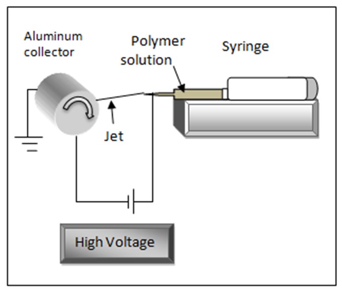
Figure 1: Schematic setup of electrospinning.
FIGURE 2
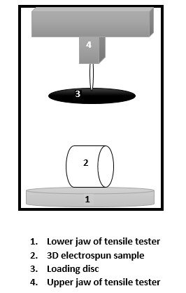
Figure 2: Schematic set up for compression by Instron tensile tester.
FIGURE 3

Figure 3: Schematic setup for indentation by Instron tensile tester.
FIGURE 4

Figure 4: Different cross-sections; circular and oval (elliptic)
FIGURE 5

Figure 5: SEM image of electrospun polyurethane layer.
FIGURE 6
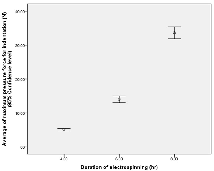
Figure 6: Effect of electrospinning duration (thickness) on the indentation force.
FIGURE 7
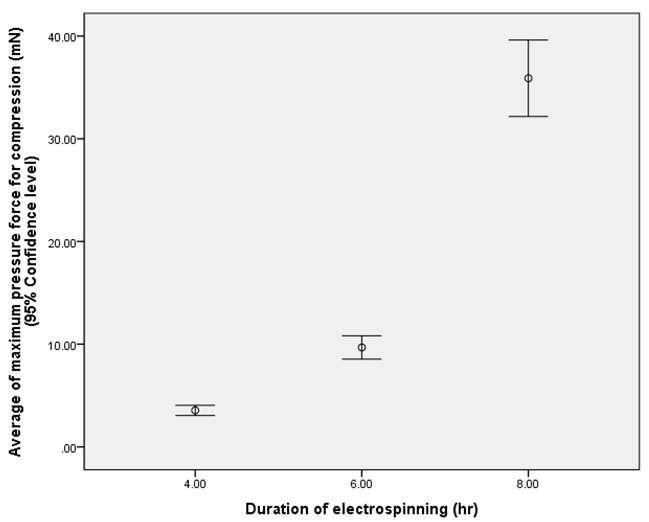
Figure 7: Effect of electrospinning duration (thickness) on compression force.
FIGURE 8
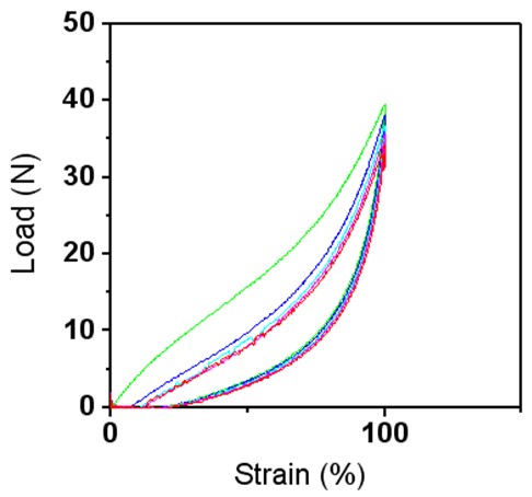
Figure 8: shows the relationship between load and strain in the cyclic loading for the electrospun PU layer.
FIGURE 9

Figure 9: The average of tension and the amount of average extension at 25%, 50%, 75%, and 100% of strain
FIGURE 10
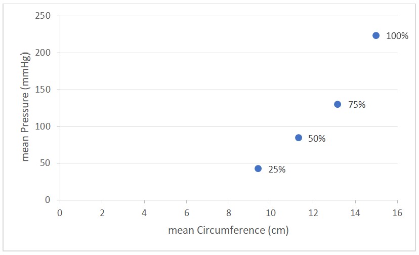
Figure 10: Average of calculated pressure of circular cross-sectional body limb at different amounts of extension different amounts of reduction factor
FIGURE 11
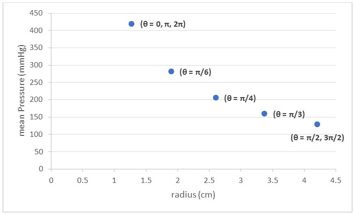
Figure 11: Average of calculated pressure for oval (Elliptic) cross-sectional body limb at different radiuses depending on the angles at 100% of strain
Tables at a glance
Figures at a glance