Piloted Pretreatment Patient-Specific Quality Assurance in Preparedness for Clinical Implementation of Intensity Modulated Radiotherapy
Received Date: May 03, 2023 Accepted Date: June 03, 2023 Published Date: June 06, 2023
doi: 10.17303/jocr.2023.4.104
Citation:Alhassan Mohammed Baidoo, Samuel Nii Adu Tagoe, Eric KT Addison, Evans Sasu (2023) Piloted Pretreatment Patient-Specific Quality Assurance in Preparedness for Clinical Implementation of Intensity Modulated RadiotherapyAccess 8: 1-6
Abstract
Background: Patient-specific QA is used to evaluate the correlation between the planned and delivered dose distributions, and the correlation depends on the treatment machine and the patient- specific QA device. Regarding this, we deem it appropriate to evaluate the performance of our patient-specific QA device before the clinical implementation of IMRT.
Methodology: Patient-specific QAs were performed for five (5) cases each for prostate and head- and-neck cancers. The IMRT plans were created with a Varian Eclipse TPS (version 13.6) and true composite with all beams at zero gantry verification plans were generated with an IBA Dosimetry miniPhantom having the MatriXX (Evolution) 2D array detector inserted into it. The verification plans were replicated on a Varian Unique Performance linear accelerator, and the dose distributions along the plane of the ionization chambers within the 2D array detector were measured and compared to those of the TPS with the aid of the myQA software, using a global gamma index analysis having the following criteria: 95% passing rate with 3% / 3 mm, and 10% low dose threshold.
Results: The passing rate of the prostate IMRT plans ranged from 95.50 to 98.43% (mean of 96.82%; standard deviation of 1.22%), whilst that of the head-and-neck ranged from 94.60 to 97.70% (mean of 96.42%; standard deviation of 1.14%). 0ne head-and-neck IMRT plan failed the gamma analysis but passed after re-planning. The measured doses compared favourably with the calculated doses (p-value = 0.029 and 0.030 for prostate and head-and-neck, respectively).
Conclusion: The study affirmed the reliability of the patient-specific QA device earmarked to be used for IMRT pre-treatment verification by our radiation oncology department. This also facilitated the development of a gamma analysis protocol for our linac and dosimeter, as well as helping to ascertain the adequacy of the acquired beam data used in commissioning our treatment planning system.
Keywords: Radiotherapy; Tumours; Heterogeneities; Intensity Modulated Radiotherapy
Introduction
Tumours usually present with very complex shapes, and coupled with the irregularity on a patient surface at the point of beam entrance as well as tissue heterogeneities within the irradiated volume would require the use of intensity-modulated (IM) beams to conform the dose distribution to the shape of the tumour (or target volume). External beam radiation therapy that relies on intensity- modulated beams is referred to as intensity modulated radiotherapy (IMRT). IMRT can also escalate doses to a certain area of the delineated target volume in a single treatment delivery phase. The treatment technique provides better dose sparing for normal tissues or critical structures close to the target volume. But the benefits of IMRT cannot be realized without proper and appropriate dosimetry, optimal geometrical tolerance of the treatment machine to be used for the treatment delivery, minimal uncertainty associated with the patient set-up and target localization, very accurate delineation of the target volume and normal tissues, and flawless transfer of treatment parameters from the treatment planning system to the treatment machine [1-3]. There is, therefore, a need to verify planned treatment parameters before treatment delivery to minimize uncertainties associated with some of the treatment delivery steps and enhance the quality of life of patients undergoing external beam radiotherapy. To augment the effectiveness and efficiency of this process, automated systems have been introduced, and have been widely embraced by the radiotherapy fraternity. Notwithstanding the acceptance, it is very imperative to evaluate the performance of these automated systems to appreciate their inherent uncertainties and limitations before clinical use. These are achievable with the implementation of efficient and effective quality assurance (QA) procedures [4,5]. How extensive are the procedures to meet the intended objectives is dependent on the treatment technique, treatment machine, and available dosimetry equipment to be used to fulfill the QA procedures [6]. Proper verification of QA procedures for the equipment and patient-specific dosimetry are imperative measures to guarantee that treatment could be delivered per treatment plans [7]. IM beams are created with the movement of the leaves of the multileaf collimator system while the beam is on during treatment delivery or by the weighted superimposition of segmented fields created with the leaves. The leaf sequencings are based on fluence maps generated via inverse planning. Hence, a realization of fluence distribution across beams before treatment delivery is paramount to any IMRT treatment [8]. Concerning this, there is a sudden increase in treatment parameters which are cumbersome if not possible to verify individually.
Since all the treatment parameters would translate into a specific dose distribution pattern within a patient, finding a way of realizing the dose distribution can serve as a means of verifying the numerous treatment parameters. Regarding this, template of a patient's IMRT plan is created and placed on a phantom with appropriate detectors embedded in the phantom. As the treatment plan with the phantom is replicated on the treatment machine, the planned dose distributions are compared to the measured one facilitating patient-specific quality assurance [2]. There is also the possibility of verifying the cumulative plan fluence distribution with the electronic portal imager attached to the opposite side of the treatment head of the linear accelerator. The doses are compared both in magnitude and spatial resolution, and a plethora of publications has given recommendations on the assessment criteria [2,9-14]. Most of the publications, irrespective of the sites, recommended a composite analysis having the following criteria: 3% dose difference, 3 mm distance to agreement (DTA), 10% low dose threshold (LDT), and 95% pass rate for both tolerance and action levels. Depending on the complexity of the treatment plan as well as the size of the target volume some literature recommends the use of an action level set at a 90% pass rate [15,16]. Regarding the calculation of the percentage difference in dose from the comparison, there are two types of gamma index methods, namely global and local gamma index analyses [5]. The global gamma index analysis calculates the percentage differences relative to the prescription dose, and the local gamma index analysis calculates the percentage differences relative to the doses at each evaluated point. The local gamma index analysis could overstate the percentage differences in the low-dose regions, while the global gamma index method could undervalue the dose discrepancies in the low-dose regions [5]. There are no clear guidelines on the choice of the gamma index analysis method for pre-treatment patient-specific QA in IMRT treatment delivery [17]. This decision needs to be made by the clinic intending to introduce IMRT treatment delivery, as the global gamma index analysis cannot substitute for the local gamma index analysis or vice versa [17]. The gamma passing rate is also dependent on the dosimeter used for the evaluation, as the configuration and the detector resolution have a great impact on the estimation of the gamma passing rates [18,19]. Regarding the reservations associated with the gamma passing rates, it is clear that the tolerance levels suggested by earlier studies or international guidelines might not always be appropriate for a particular institution dosimeter [17].
The gamma passing rates are, therefore, dependent on the types of gamma analyses, dosimeters, and linear accelerators (linacs) to be used [17]. Regarding the above, it is necessary for institutions wishing to introduce IMRT to appreciate limitations with their dosimeters for patient-specific QAs as well as their linacs, and circumspectly establish their own gamma analysis protocol by determining the type of gamma index analysis and the gamma criteria suitable for their linacs and dosimeter
Therefore, we find it necessary to thoroughly evaluate the performance of our patient-specific QA devices and the adequacy of the commissioning data to be able to establish gamma analysis protocol for our institution before clinical use of the IMRT technique.
Materials and Methods
A miniPhantom with a MatriXX Evolution 2D array detector (IBA Dosimetry Gmbh, Germany) inserted into it, earmarked for patient-specific QA by the radiation oncology department, was scanned with a Discovery RT 590 CT-simulator (General Electric, USA) as shown in Figure 1. The scanning parameters were selected following departmental protocol for patient CT data acquisition for computerized treatment planning. Inscription lines placed on the surfaces of the miniPhantom by the phantom manufacturer and the lasers (patient position system) within the imaging room were used to align the phantom within the aperture of the CT scanner. Where the inscription lines crossed each other was set as the reference point for the imaging, and this reference point was defined as the origin for the computerized treatment planning with the miniPhantom. The axial CT data set of the miniPhantom and detector were exported to an Eclipse treatment planning system (version 13.5; Varian Medical Systems, Palo Alto, USA). Samples of the axial CT slices of the miniPhantom are depicted in Figure 2.
Five cases each of patients with prostate and head-and-neck cancers who had had their treatment with 3D conformal radiotherapy, such that the treatments were planned with the Eclipse TPS, were selected and IMRT plans created for them. For the prostate cases, the plans were created using seven fields that were evenly distributed in coplanar directions with the sliding window technique. The same irradiation geometry approaches were used for the head-and-neck cases, but the fields ranged from seven to nine depending on the achievable dose optimization. The optimization goal was to ensure that at least 95% of the volume of the targets received the prescribed dose and that the maximal dose of the targets would not exceed 109% of the prescribed dose. The IMRT plans were evaluated such that each one satisfied the adopted departmental dose tolerances and constraints for organs at risk (or normal tissues) displayed in Table 1 [20]. After the optimization processes, dose calculations were performed using anisotropic analytical algorithm (AAA) version 13.6 with a grid size of 2.5 mm. For each IMRT plan, a verification plan was generated with the mini Phantom for a single fraction dose. A true composite with all beam gantry angles set at zero degrees was used for each verification plan. Figure 3 shows a planning window of the TPS for a prostate IMRT plan and its verification plan. All the treatment simulations were performed with single energy (6 MV) Unique Performance medical linear accelerator (Varian Medical System, Palo Alto, USA) equipped with the Varian Millennium 120- leaf MLC (Varian Medical System, Palo Alto, USA). The radiotherapy plan doses in a DICOM format (RTDOSEs) for the miniPhantom for the various IMRT plans were exported to a folder created on the TPS desktop and then transferred onto a dedicated pen drive. The RTDOSEs on the pen drive were transferred onto a folder created on the desktop of a laptop having the myQA software (IBA Dosimetry Gmbh, Germany).
The mini Phantom setup for the plan verifications was reproduced on the Unique Performance linear accelerator such that the source-to-detector distance was 100 cm. The 2D array detector within the mini Phantom was connected to the laptop having the myQA software via Ethernet cable. The clinic and the treatment machine were set up and selected from the menu of the myQA software. The detector was also selected from the menu. The 2D array detector was pre-irradiated with a field size of 24 cm x 24 cm for 500 MU, and then calibrated against a Farmer-type ionization chamber having a calibration coefficient traceable to the secondary standard dosimetry of IBA Dosimetry Gmbh, Germany. The calibration was based on the IAEA-TRS 398 protocol [22]. The detector calibration procedures recommended by the detector manufacturer were also followed [21]. The calibration of the 2D array detector was affirmed by simulating with the TPS a 2 Gy dose delivery along the beam central axis for a field size of 10 cm x 10 cm with the mini Phantom setup and replicating the dose delivery on the linear accelerator. The correlation between the measured and the TPS calculated doses was then evaluated.
For the patient-specific QAs, anonymous names were used to create the respective patients within the myQA software and then a project was created for each patient. The appropriate RTDOSE for a specific patient was imported into the created project for the patient, and the process was repeated for all of the patients. The verification plan for each patient was replicated on the Unique Performance linear accelerator, and in the measurement mode of the myQA software, the dose distribution along the plane of the detector perpendicular to the beam central axis was measured with the detector using a single shot continuous acquisition mode, such that the measurement was initiated and stopped manually. At each time of measurement, it was ensured that the detector had been pre-irradiated with the required field size and number of monitor units before the commencement of the measurements. The setup for the patient-specific quality assurance is depicted in Figure 4. For each patient’s dose comparison, the project explorer window of the myQA software was accessed; from the measurement folder the measured data was dragged to the compare pane, and from the import folder the dose plan (corresponding to the calculated dose distribution along the plane of the detector) was also dragged to the reference pane. The images in the reference and compare panes were aligned so that they were superimposed perfectly as much as possible using tools provided within the menu of myQA software [21]. A dose comparison window of the myQA software is shown in Figure 5 for one IMRT plan for the prostate. Gamma index calculation was then performed for each patient using the following criteria: 3% dose difference (at 5% threshold), 3 mm distance to agreement, and 95% passing rate with a 10% low dose threshold. The verification results within the result pane of the software were recorded for each patient. The patient-specific quality assurance for each patient was repeated three consecutive times on different days to check the constancy in response to the detector. This also served as a means of checking the performance of sensors within the detector for monitoring environmental air-density variations, which are used by the detector to automatically correct for the effects of temperature and pressure on the readings of the various vented ionization chambers within the detector.
The dose measurements with the 2D array detector for all the IMRT plans were repeated with a Farmer-type ionization chamber (FC65-G; IBA Dosimetry GmbH, Germany) held in a dedicated insert (provided by the manufacturer of the mini Phantom) which was used to replace the 2D array detector within the mini Phantom. During the measurements, the ionization chamber was connected to a UNIDOS electrometer (PTW-Freiburg, Germany) which was set to measure charges in radiation trigger mode with a bias voltage of +400 V. Before these measurements with the ionization chamber, the mini Phantom with the ionization chamber was also scanned with the CT simulator and the axial images exported to the TPS. The sensitive volume of the ionization chamber was contoured (delineated), and each verification plan dose was prescribed to the contoured sensitive volume of the ionization chamber. The verification plans generated for the mini Phantom and the ionization chamber were replicated on the linear accelerator.
Results
In Table 2 is listed the ionization chamber measured doses and their corresponding calculated doses by the TPS for the various IMRT plans verified with the mini Phantom and the ionization chamber. The difference between the measured and the calculated doses for each IMRT plan is also presented. Each difference in a dose per IMRT plan/ patient is expressed as a percentage of the respectively measured dose for each case and presented in Table 2. The Gamma passing rates of the various prostate and head-and-neck IMRT plans verified on the three consecutive days are listed in Table 3. Also presented is the mean gamma passing rate for each IMRT plan for the consecutive days. The mean gamma passing rate for each IMRT plan for the consecutive days per patient is illustrated as bar charts for prostate and head-and-neck cases in Figure 6. The uncertainties associated with the passing rates are shown as error bar captions on the various bars representing individual gamma passing rates. The blue bars represent gamma passing rates for patients and the red bars are used to denote recommended gamma passing rates.
Among the limitations of the study are the inaccessibility of different types of 2D detector arrays and corresponding software to compare measured dose distributions recorded with MatriXX for a variety of relevant information on detector response to the measured dose distributions. The restriction to one type of medical linear accelerator also limited the study to only a Varian linac, as well as the limitation of GI method in which it only determines the number of points out of tolerance without giving any information about their spatial location.
Discussion
A 5% uncertainty in dose calculation tends to result in 20% changes in the local tumour control probability and 30% changes in the normal tissue complication probability [23-25]. Regarding this, accurate dose calculations are, therefore, essential for radiotherapy treatment planning, and the error in dose calculation must be less than 3% [25-26]. Concerning these and our experience with IMRT treatment delivery informed our decision to use the gamma analysis criteria of 3%/ 3 mm for this study. Many steps are involved in external beam radiotherapy, and each comes with some uncertainty. Regarding this, reducing the error margin for the dose calculation would make room for the inclusion and relaxation of stringent requirements of some of the steps involved in the treatment delivery, such that when the associated errors of the several steps are summed up in quadrature, the resultant error will be within the recommended tolerance [27]. From the gamma analyses, the highest gamma passing rate was recorded for a prostate IMRT plan, and also, the gamma passing rates for the prostate IMRT plans were better than those of the head-and-neck IMRT plans. The average gamma passing rates for the consecutive verifications ranged from 95.50 to 98.43% (mean of 96.82 ± 1.22%) for the prostate IMRT plans and 94.6 to 94.6 to 97.70% (mean of 96.82 ± 1.15%) for the head-and-neck IMRT plans. These can be attributed to the complexity of the head- and-neck target volumes and the tissue density heterogeneities within the head-and-neck region compared to those of the prostate and the pelvic region, respectively [25]. Also, for most of the head-and-neck cancer cases, large field sizes were used for the treatment planning owing to the size of the target volumes and the need to apply angular collimation to the beams to minimise the tongue-and-groove effect on the dose distributions [28]. The large fields with a width greater than 14 cm were split into two or more carriage movements (or split-fields) during the dose calculations process as the modulation travel distances of the MLCs were exceeded by the large fields. The segmentation of the large fields is known to reduce the accuracy of the calculated dose distributions for IMRT plans [29,30]. From Table 3, although the gamma passing rates of the IMRT plans were very encouraging, we had anticipated that they would have ranged between 97 to 100% based on the results of other studies performed with a similar detector [31-33]. Beam data used to commission the treatment planning system such as dynamic leaf gap (DLG) and MLC leaf transmission parameters can influence dose accuracy in IMRT treatment delivery thus impacting the gamma passing rate [34-38]. Regarding this, the measured DLG for the treatment machine had been upwards adjusted via alterations to obtain an optimal value that would improve the dose accuracy, but no adjustments had been applied to the measured leaf transmission parameters. The tweaking of the DLG was done before this study. It is recommended that during the commissioning of a medical linear accelerator specifically for IMRT treatment delivery, beam data should be acquired for field sizes ranging from 1 x 1 to 40 x 40 cm2 and lower depending on the TPS vendor requirements (Das et al., 2008). But during the commissioning of the linear accelerator that was used for this study, beam data were acquired for field sizes ranging from 2 x 2 to 40 x 40 cm2 due to the non-availability of appropriate detectors to measure the dosimetric parameters below the field size of 2 x 2 cm2 and the need not to under or overestimate the relative dose factors of field sizes below the minimum field size for beam data acquisition which will have ramification on the accuracy of IMRT plan doses [36]. However, [39] had shown that including field sizes below 2 x 2 cm2 in beam data acquisitions during commissioning would not have any significant impact on the dose accuracy of IMRT plans [39]. Hence to improve the gamma passing rates we should focus on also tweaking the leaf transmission parameters. Concerning these, results of the ionization chamber measurements listed in Table 2, and the illustrations provided in Figure 6, we can affirm that the commissioned beam data are adequate and reliable for IMRT treatment delivery. The ionization chamber measured doses compared very well to their calculated counterparts by the TPS with a standard error of less than 1%. This shows that the ionization chamber measurements cannot be used as surrogates for the gamma indexes, but may be used to verify high dose deviation point/ region within a comparison dose map for gamma analyses. The consecutive verification measurements with the 2D array detector have an error of less than 1%, and this attests to the constancy and stability of the detector for patient-specific quality assurance. The MatriXX 2D array detector is, therefore, suitable for IMRT dosimetric verification, but there is also the need for us to study its angular dependence as it is always good to use true composite with gantry angles at the required angles as planned for the IMRT dosimetric verification.
Gamma indexes of 95% pass rate at 3%/ 3 mm are currently accepted as the departmental protocol for patient-specific quality assurance.
Conclusion
The piloted patient-specific quality assurance offered us the opportunity to verify the adequacy and reliability of beam data acquired during the commissioning of a medical linear accelerator earmarked for IMRT treatment delivery. This study has also affirmed the suitability of the MatriXX 2D array detector for patient-specific quality assurance, and the development of gamma analysis protocol for the detector and the linear accelerator.
- Cheung KY (2006) Intensity modulated radiotherapy: advantages, limitations and future developments. Biomed Imaging Interv J 2: e19.
- Pan Y, Yang R, Zhang S, Li J, Dai J, Wang J, Cai J (2019) National survey of patient specific IMRT quality assurance in China. Radiation Oncology 14: 69.
- Stralingsdosimetrie NCV, Commissie N, Stralingsdosimetrie V, Stralingsdosimetrie NCV (2013) Code of practice for the quality assurance and control for intensity modulated radiotherapy.
- Cyriac S, Musthafa MM, Ganapathi Raman R, Abdul Haneefa K, Hridya VT (2014) Pretreatment patient specific quality assurance and gamma index variation study in gantry dependent EPID positions for IMRT prostate treatments. Journal of Radiotherapy.
- Ezzell GA, Burmeister JW, Dogan N, LoSasso TJ, Mechalakos JG et al. (2009) IMRT commissioning: multiple institution planning and dosimetry comparisons, a report from AAPM Task Group 119. Medical physics 36: 5359-73.
- Stojadinovic S, Ouyang L, Gu X, Pompoš A, Bao Q, Solberg TD (2015) Breaking bad IMRT QA practice. Journal of applied clinical medical physics 16: 154-65.
- Ravichandran R, Bhasi S, Binukumar JP, Davis CA (2011) Need of patient- specific quality assurance and pre-treatment verification program for special plans in radiotherapy. Journal of Medical Physics/Association of Medical Physicists of India 36: 181.
- Tagoe SN, Mensah SY, Fletcher JJ (2018) Implementation of compensator- based intensity modulated radiotherapy with a conventional telecobalt machine using missing tissue approach. Polish Journal of Medical Physics and Engineering 24: 171-9.
- Miften M, Olch A, Mihailidis D, Moran J, Pawlicki T et al. (2018) Tolerance limits and methodologies for IMRT measurement‐ based verification QA: recommendations of AAPM Task Group No. 218. Medical physics 45: e53-83.
- Kang DJ, Jung JY, Kim JH, Park S, Lee KS et al. (2012) The patient specific QA of IMRT and VMAT through the AAPM task group report 119. Journal of radiological science and technology 35: 255-63.
- Mancuso GM, Fontenot JD, Gibbons JP, Parker BC (2012) Comparison of action levels for patient‐ specific quality assurance of intensity modulated radiation therapy and volumetric modulated arc therapy treatments. Medical physics 39: 4378-85.
- Mehrens H, Taylor P, Followill DS et al. (2020) Survey results of 3D-CRT and IMRT quality assurance practice. J Appl Clin Med Phys 21: 70-6.
- Van der Wal E, Wiersma J, Ausma AH et al. (2013) NCS Report 22: Code of Practice for the Quality Assurance and Control for Intensity Modulated Radiotherapy. Delft: Netherlands Commission on Radiation Dosimetry.
- Mans A, Schuring D, Arends MP et al. (2016) The NCS code of practice for the quality assurance and control for volumetric modulated arc therapy. Phys Med Biol 61: 7221-35.
- Mans A, Schuring D, Arends MP, Vugts CA, Wolthaus JW et al. (2016) The NCS code of practice for the quality assurance and control for volumetric modulated arc therapy. Physics in Medicine & Biology 61: 7221.
- Heilemann G, Poppe B, Laub W (2013) On the sensitivity of common gamma index evaluation methods to MLC misalignments in Rapidarc quality assurance. Med Phys 40: 031702.
- Park JM, Kim J, Park S, Oh D H, Kim S (2018) Reliability of the gamma index analysis as a verification method of volumetric modulated arc therapy plans. Radiation Oncology 13: 175.
- Hussein M, Rowshanfarzad P, Ebert MA, Nisbet A, Clark CH. A comparison of the gamma index analysis in various commercial IMRT/VMAT QA systems.
- Fredh A, Scherman JB, Fog LS (2013) Munck af Rosenschold P. Patient QA systems for rotational radiation therapy: a comparative experimental study with intentional errors. Med Phys 40: 031716.
- Emami B, Lyman J, Brown A et al. (1991) Tolerance of normal tissue to therapeutic radiation.Int J Radiat Oncol Biol Phys 21: 109-22.
- myQA User's Guide – Vol.5. myQA Patients. IBA Dosimetry GmbH. 2017.
- International Atomic Energy Agency (IAEA) (2000) Technical Report Series 398. Absorbed Dose Determination in External Beam Radiotherapy-An International Code of Practice for Dosimetry Based on Standards of Absorbed Dose to Water. IAEA.
- Haga A, Magome T, Takenaka S et al. (2014) Independent absorbed-dose calculation using the Monte Carlo algorithm in volumetric modulated arc therapy. Radiat Oncol 9: 75.
- Kry SF, Glenn MC, Peterson CB et al. (2019) Independent recalculation outperforms traditional measurement-based IMRT QA methods in detecting unacceptable plans. Med Phys 46: 3700-8.
- Shen Z, Tan X, Li S et al. (2021) Correlation between the γ passing rates of IMRT plans and the volumes of air cavities and bony structures in head and neck cancer. Radiat Oncol 16: 134.
- Chetty IJ, Curran B, Cygler JE et al. (2007) Report of the AAPM Task Group No. 105: Issues associated with clinical implementation of Monte Carlo-based photon and electron external beam treatment planning. Med Phys 34: 4818-53.
- van Herk M (2004) Errors and margins in radiotherapy, Seminars in Radiation Oncology 14: 52-64.
- Su Hf, Zhao M, Zhang J, Dai Zt (2021) Dosimetric effects related to collimator angle optimization in intensity-modulated radiotherapy planning for gastric cancer. Prec. Radiat. Oncol 5: 25-33.
- Gary A, Ezzell, Jay W, Burmeister, Nesrin Dogan Thomas J et al. (2009) IMRT commissioning: Multiple institution planning and dosimetry comparisons, a report from AAPM Task Group 119. November 2009. Med. Phys 36: 5359-73.
- Lee CC, Wu A, Garg M, Mutyala S, Kalnicki S (2011) A new approach to reduce number of split fields in large field IMRT. Med Dosim. 2011 Spring 36: 1-5.
- Briceno J, Mckinsey RD, Esquivel C, Mavroidis C et al. (2013) Patient Specific IMRT QA Analysis Comparison of Four Commercially Available Systems. Medical Physics 40: 251.
- Son J, Baek T, Lee B, Shin D, Park SY et al. (2015) A comparison of the quality assurance of four dosimetric tools for intensity modulated radiation therapy. Radiol Oncol 49: 307-13.
- Madhusudhana Sresty NVN, Raju AK, Reddy BN, Sahithya VC, Mohmd Y et al. (2019) Evaluation and Validation of IBA I'MatriXX Array for Patient-Specific Quality Assurance of TomoTherapy®. J Med Phys 44: 222-7.
- Masaru Isono, Yuichi Akino, Hirokazu Mizuno, Yoshihiro Tanaka, Norihisa Masai et al. (2020) Inter-unit variability of multi-leaf collimator parameters for IMRT and VMAT treatment planning: a multi-institutional survey, Journal of Radiation Research 61: 307-13.
- Jinkoo Kim, James S Han, An Ting Hsia, Shidong Li, Zhigang Xu, Samuel Ryu, Relationship between dosimetric leaf gap and dose calculation errors for high definition multi-leaf collimators in radiotherapy, Physics and Imaging in Radiation Oncology 5: 31-6.
- Azimi R, Alaei P, Higgins P (2012) The effect of small field output factor measurements on IMRT dosimetry. Med Phys 39: 4691-4.
- Ravindra Shende, Ganesh Patel (2017) Validation of Dosimetric Leaf Gap (DLG) prior to its implementation in Treatment Planning System (TPS): TrueBeam™ millennium 120 leaf MLC, Reports of Practical Oncology & Radiotherapy 22: 485-94.
- Petersen N, Perrin D, Newhauser W, Zhang R (2017) Impact of Multileaf Collimator Configuration Parameters on the Dosimetric Accuracy of 6-MV Intensity-Modulated Radiation Therapy Treatment Plans. J Med Phys 42: 151-5.
- Niyomthai T, Tuntipumiamorn L, Damrongkijudom N, Tangboonduangjit P (2012) Effect of Small Field Dosimetry on Accuracy of Dose Calculation Using AAA 8.6 Algorithm in Head and Neck IMRT. 6th Annual Scientific Meeting, Phitsanulok, Thailand 23-6.
- Abdel-Wahab M, Bourque JM, Pynda Y, Iżewska J, Van der Merwe D et al. (2013) Status of radiotherapy resources in Africa: an International Atomic Energy Agency analysis. The lancet oncology 14: e168-75.
- Andreo P, Huq MS, Westermark M, Song H, Tilikidis A et al. (2002) Protocols for the dosimetry of high-energy photon and electron beams: a comparison of the IAEA TRS-398 and previous international codes of practice. International Atomic Energy Agency. Phys Med Biol 47: 3033-53.
- Brandon Koger, Ryan Price, Da Wang, Dolla Toomeh, Sarah Geneser, Eric Ford (2020) Impact of the MLC leaf‐ tip model in a commercial TPS: Dose calculation limitations and IROC‐ H phantom failures. J Appl Clin Med Phys 21: 82-8.
- Indra J Das, Chee-Wai Cheng, Ronald J Watts, Anders Ahnesjö, John Gibbons (2008) Accelerator beam data commissioning equipment and procedures: Report of the TG-106 of the Therapy Physics Committee of the AAPM Med. Phys 35: 4186-215.
- Low DA, Moran JM, Dempsey JF, Dong L, Oldham M (2011) Dosimetry tools and techniques for IMRT. Medical physics 38: 1313-38.
- Miften M, Olch A, Mihailidis D, Moran J, Pawlicki T et al. (2018) Tolerance limits and methodologies for IMRT measurement‐based verification QA: recommendations of AAPM Task Group No. 218. Medical physics 45: e53-83.
- Radiother Oncol (2013) 109: 370-6.
- Reft C, Alecu R, Das IJ, Gerbi BJ, Keall P et al. (2003) Dosimetric considerations for patients with HIP prostheses undergoing pelvic irradiation. Report of the AAPM Radiation Therapy Committee Task Group 63. Medical physics 30: 1162-82.
- Stasi M, Bresciani S, Miranti A, Maggio A, Sapino V, Gabriele P (2012) Pretreatment patient‐specific IMRT quality assurance: a correlation study between gamma index and patient clinical dose volume histogram. Medical physics 39: 7626-34.
FIGURE 1
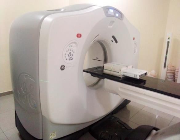
Figure 1: CT scanning of the miniPhantom with the MatriXX 2D array detector embedded in it
FIGURE 2
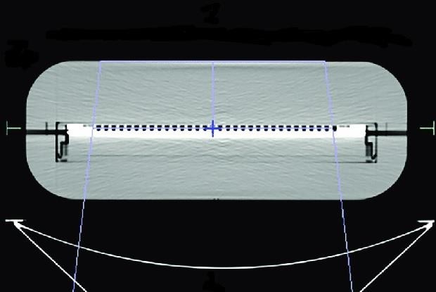
Figure 2: Axial CT slice of the miniPhantom and 2D array detector
FIGURE 3
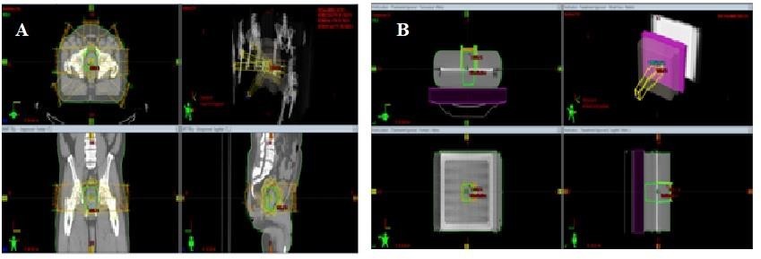
Figure 3: TPS planning window: A. prostate IMRT plan, B. Verification plan
FIGURE 4
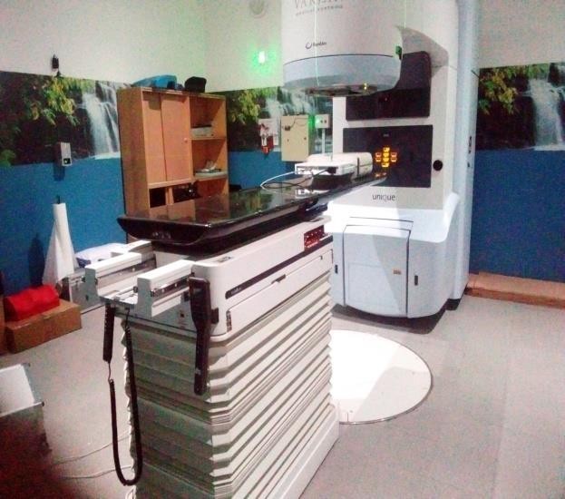
Figure 4: Treatment delivery with the miniPhantom having the MatriXX detector inserted into the phantom
FIGURE 5
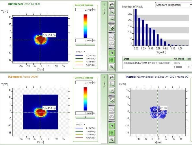
Figure 5: Dose comparison window of myQA software
FIGURE 6
.JPG)
Figure 6(a): Gamma passing rates of IMRT plans for (a) prostate
.JPG)
Figure 6(b): Gamma passing rates of IMRT plans for (b) head-and-neck cases
Tables at a glance
Figures at a glance