Streak Artifacts due to Change in Reconstruction Parameters in CT in PET-CT Image Acquisition
Received Date: April 02, 2025 Accepted Date: April 15, 2025 Published Date: April 19, 2025
doi: 10.17303/jrnm.2025.2.102
Citation: SV Ramana murthy, KB Sricharan, K Rajakumar, K Jaya Udaya Sekhar, Sanjay Kumar (2025) Streak Artifacts due to Change in Reconstruction Parameters in CT in PET-CT Image Acquisition. J Radiol Nucl Med 2: 1-6
Abstract
An artifact in CT can be either patient related, machine related or due to change in image processing techniques. Ihe pa- tient related and image processing related artifacts can be resolved or corrected by being alert, proper instruction to the patient and applying software correction techniques.
We encountered an artifact on the thoracic and abdominal region of Trans axial computed tomography (CT) images in the PET-CT (Positron emission computed tomography) scan of each patient throughout the day. Which were showed near spiral streaks across Tran's axial images.
The streak artifact is software or reconstruction-based artifact caused due to CT acquisition parameters mismatch. We describe a rare cause of the streak artifact that appeared on a Tran's axial CT image because of change in CT parameters like scan type, rotation time, recon recon type, pitch, noise index and all.
Keywords: Streak Artifact; Hardware; Computed Tomography; Trans-Axial; Reconstruction Parameters
Introduction
Positron emission computed tomography (PET) combined with computed tomography (CT) is an imaging technique used in oncology, cardiology and neurolcv. CI' is essential for attenuation correction for PET data, anatomi- cal information and Ixalization of the PET radiotracer up- take within the patient's body. There is an important role in ensuring the CT acquisition parameters in PET-CT scan to optimize to provide the minimum possible radiation dose to the patient with good image quality.
Artifacts and image quality are two sides of the same coin. An artifact in a computed tomography (CT) im- age can be difference in the Hounsfield unit (HU) seen in the image obtained as opposed to what we expected [1]
An artifact in CT can be either patient related, equipment (Hard ware) related or due to change in image processing. Most of the patient related and image processing related artifacts can be corrected or avoided by being alert, properly instruct to the patient and also applying soft- ware corrections [2-41.
Case Report
Our department has a positron emission comput- ed tomography (PET-CT) scanner (Mcxåel discovery IQ 5 ring, s/n We encountered an artifact on the thoracic and pelvic region of Tran's axial CT images in the PET-CT scan of each patient throughout the day. Which were showed near spiral streaks across Tran's axial images? On careful examination and in particular viewing CT images in IX)ne and abdominal window, it became ap- parent that the streaks in the Trans axial slices were spiral at thoracic and pelvic region. The remaining slices did not show this kind of artifacts. The artifact persistent on the CI' scan even after cleaning of the mylor window with warm wa- ter or disinfect solution. We felt that the possible reason for the artifact could due to defect in the collimation of X- rays.
We immediately made a call to service engineer and find insufficient dialectical oil [Figure and while opening CT gantry for filling the dielectric oil to the CT tubes he found breakdown at the HV cathode cable (Figure ICI. Immediately placed an order for the spare part and re- placed it on an emergency basis. After that service engineer done all CT QA and QC calibration procedures but later we again found the same artifacts on the CT Trans axial images of all and PET-CT scan-based patients. Then GE engineer suspected on the CT acquisition, reconstruction meth- ods and we decided to review the CT parameters like scan type, rotation time, recon mode, recon type, pitch, noise index and all. Our review revealed difference in CT reconstruction type and rotation time.
In the earlier protocol the standard recon type and rotation time was 0.6sec with standard recon mode which was now changed to soft recon type, IQ enhance recon mode with rotation time of 0.7sec.
IQ enhance (IQE) enables faster anatomical cover- age using faster helical scanning at similar artifact index lev- el compared to slower helical scanning without IQE. This coverage speed equivalent to that of wider detectors (32slice equivalent) at same table speed.
Discussion
Streak artifacts occur near materials like metals or bone primarily as a result of beam hardening and scatter, This artifact looks like dark streaks between metal, bone, io- dinated contrast, barium and other high attenuation mate- rials and also bright streaks are seen adjacent to the dark streaks [5].
X-rays lose their energy or harden more quickly as they pass through metal or bone than they pass through muscles or organs. These streaking artifacts can appear in Trans axial images of computed tomography due to electri- cal fluctuations and collimation defects.
This artifact is also called as Compton scatter and scatter causes X-ray photon to change in direction and ener- gy. Due to this could end up in a different detector than they should be in.
The use Of metal artifact reduction of CIS for atten- uation in combined PET-CT is always recommended. Nowadays iterative metal artifact reduction software was ins- talled in PET-CI' machines. Which is suppress the streak ar- tifacts by decreasing the HU in areas in which values have been overestimated and by increased HU in areas of under. estimation [6].
A higher KV scan can also attempted by tech- nologists to prcxiuce a harder X-ray beam and, consequent. ly, fewer beam hardening artifacts. There is a trade-off, though, since a higher KV will result in a lower scan's tissue contrast.
If your reconstruction techniques and reduction software are current and also doing the scans with highest KV but streak artifacts are still appearing. It's probably time to call in a service engineer to diagnose underlying causes and also check acquisition reconstruction parameters.
Conclusion
The streaking artifacts on trans axial CT images due to an unusual cause such as improper acquisition pa. rameters which does not require expensive replacement of the detector CT hardware parts and also not much of significant down time. This type of artifacts can be avoid. ed by maintaining locking system of the standard protocols prescribed by the manufacturer.
- Seeram E (2001) Image quality. In: Computed Tomography: Physical Principles, Clinical Applications and Quality Control. 2nd ed. Philadelphia, PA: Saunders; 17499.
- Barrett JF, Keat N (2004) Artifacts in CT: Recognition and avoidance. Radio graphics, 24:167991.
- Jha AK, Purandare NC, Shah S, Agrawal A, Puranik AD, Rangarajan V (2013) Identification Of a unique Cause Of ring artefact seen in computed tomography transaxial im- ages. Indian J Nucl Med, 28:2323.
- Jha AK, Shah S, Agrawal A, Purandare NC, Puranik AD, Rangarajan V (2013) Stairstep artefact seen in coronal and sagittal reformatted images because of misalignment of computed tomography tube, in a positron emission tomography/computed tomography scanner. Indian J Nucl Med, 28: 1834.
- Hsieh J (2003) Computed Tomography: Principles, Design, Artifacts, and Recent Advances. Bellingham, Washington, USA: SPIE Press; 1907.
- Charlotte S van der Vos, Anne I J Arens, James J Hamill, Christian Hofmann, Vladimir Y Panin, et al. (2017) Metal Artifact Reduction of CT Scans to Improve PET/CT, 58: 1867-72.
FIGURE 1
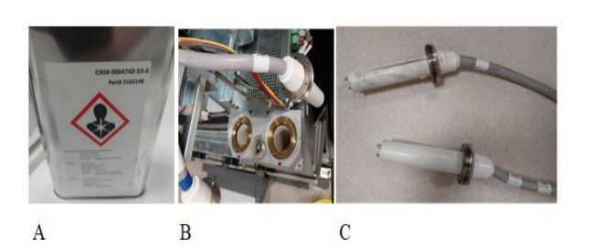
Figure 1: a) Dialectical Oil b) placement zone c) HV cathode cables
FIGURE 2
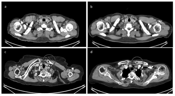
Figure 2: (a)&(c) axial images of two different patients showing streaking artifacts at clavicle bone (encircled) and axial images of same patients after changing parameters
FIGURE 3
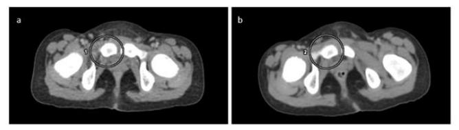
Figure 3: (a) axial image of another patient showing streaking artifact at right pubic bone (encircled) and (b) axial image of the same patient after changing parameters
Figures at a glance